
Related Manuals for Autoscript Control Net HC-1


Summary of Contents for Autoscript Control Net HC-1
- Page 1 Control Net Controllers and Smart Combiner Part Nos. HC-1 MFC-D www.autoscript.tv...
- Page 2 Copyright © 2014 All rights reserved. Original Instructions: English All rights reserved throughout the world. No part of this document may be stored in a retrieval system, transmitted, copied or reproduced in any way, including, but not limited to, photocopy, photograph, magnetic or other record without the prior agreement and permission in writing of the Vitec Group plc.
-
Page 3: Table Of Contents
Contents Safety..........2 Troubleshooting . -
Page 4: Safety
Safety Electrical Connection Important information on the safe installation and operation of this product. Read this information before operating the product. WARNING! Risk of electric shock. Always check cables for For your personal safety, read these instructions. Do not operate signs of damage. -
Page 5: About This Guide
Safety and About this Guide Water, Moisture and Dust WARNING! The fitting of non-approved parts and accessories, or the carrying out of non-approved alterations WARNING! Protect the product from water, moisture and or servicing can be dangerous and could affect the safety of dust. -
Page 6: Components And Connections
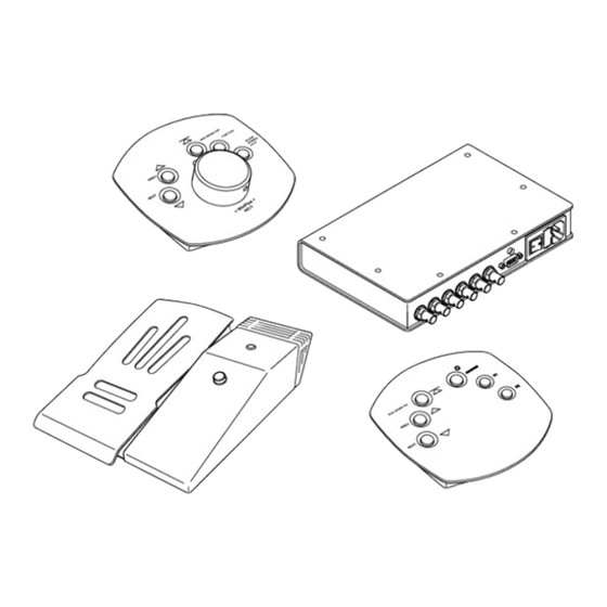
Components and Connections Key Components Hand Controller - Front View Hand Controller - Rear View ‘Next story’ button Scroll control indication LED ‘Previous story’ button DC power socket ‘Back to top of script’ button Serial control socket Programmable function button 1 Control Net socket ‘Blank screen’... - Page 7 Components and Connections Foot Controller- Front View Foot Controller - Rear View Cable guard removed for illustrative purposes Forward scroll control foot pedal DC power socket Direction indicator LED Control Net connector Cable guard Serial connector for MFC-D (RJ11) Reverse scroll control button Serial connector (9 way D type)
- Page 8 Components and Connections Desk Controller- Front View Desk Controller - Bottom View ‘Next story’ button Serial connector (RJ11) ‘Previous story’ button Cable strain relief clamp ‘Back to top of script’ button Toggle reverse button Scroll direction indicator LED Function button 1 Function button 2...
- Page 9 Components and Connections Smart Combiner Box Power indicator LED Serial connector (9 way D type) AC power inlet socket Control Net input or expansion loop output Fuse holder Control Net inputs Power switch...
-
Page 10: Box Contents
Components and Connections Box Contents Foot Controller Package - MFC-PKG1 Hand Controller Part Description HC-1 Five button optical hand control Smart Combiner Part Description Magnetic foot control MFC-D Desk controller PSU-HR Hirose power supply Part Description RJ11-2 RJ11 connecting cable, 2 metres RJ11-5 RJ11 connecting cable, 5metres Smart combiner box... -
Page 11: Tools Required
Components and Connections Tools Required Pozidriv® PZ-1 screwdriver. -
Page 12: Installation
Installation Controller Connection Options Control Net Connections Special consideration should be given when choosing locations and Control Net connections should always be made with connection methods to install and use the controllers and smart screened 75Ω coaxial cable.The cable screen must be combiner box. -
Page 13: Serial Connections
Installation Smart Combiner Box Serial Connections The smart combiner box has six Control Net inputs available. One of Single controllers can also be connected using a serial connection. The the inputs can also be used as an output to either link back to the serial connection can also provide power to the connected controller. - Page 14 Installation Desk Controller Strain Relief Clamp The desk controller is fitted with a strain relief clamp which must be The desk controller is connected with a short local serial link to the foot used to prevent the cable from becoming disconnected during use. controller using an RJ11 connecting cable.
-
Page 15: Power Connections
Installation Smart Combiner Box Foot Controller The smart combiner box has a serial out connector. This can be used to connect it directly to the control system. 12VDC Desk Controller The desk controller receives DC power via the RJ11 serial connection, and does not require a separate connection. -
Page 16: System Connections - Single Controllers
Installation System Connections - Single Controllers XBox and WinPlus Host PC Control Net connections Ω BNC coax cables) Serial connections (9-pin D connecting cable) Serial connections (RJ11 connecting cable) Foot Controller Power Supply Hand Controller Desk Controller PSU-HR is required for a controller not connected using a serial link... -
Page 17: System Connections - One Smart Combiner Box
Installation System Connections - One Smart Combiner Box XBox and WinPlus Host PC The diagram shows an example of an installation using one smart combiner box. Any combination of controllers (hand or foot and desk) can be used. Six Control Net inputs available on the smart combiner (five if Foot and Desk Controllers the Control Net output is used... -
Page 18: System Connections - Two Smart Combiner Boxes
Installation System Connections - Two Smart Combiner Boxes Five controllers (mixed) XBox and WinPlus Host PC connected to the first smart combiner Smart Combiner Box(1) Additional five controllers (mixed) connected to the second smart combiner Control Net loop out to second smart combiner Smart Combiner Box(2) -
Page 19: Adding Additional Smart Combiner Boxes
Installation Adding Additional Smart Combiner Boxes Powering Up Additional hand, foot and desk controllers can be added into a system The hand, foot and desk controllers are automatically powered up when by looping more smart combiner boxes onto the Control Net. DC power is connected. -
Page 20: Operation
Operation Using the Hand Controller Story Control Buttons The hand controller is typically located in the control room and operated in close conjunction with the WinPlus software. The scroll speed and direction of the prompted text is controlled using a rotary dial. Push buttons are provided for next and previous pages/stories selection and other functions described in this section. - Page 21 Operation Button Illumination Function Control Buttons When selected, the function buttons illuminate (F1 yellow, F2 red). Scroll Control Indicator When the scroll control dial is being operated (i.e. not in the indented stop position), an indicator LED alerts the operator. Function button - This can be programmed through WinPlus for various functions, or controls devices through a general purpose interface.
-
Page 22: Using The Foot Controller
Operation Using the Foot Controller Prompter Text Reverse Control The foot controller can be placed in a convenient location on the floor to allow the operator to control the speed of the prompted text discreetly and completely hands free. The prompted text is controlled using a frictionless magnetic foot pad. -
Page 23: Using The Desk Controller
Operation Direction Indicator LED Story Control Buttons When the foot controller is being operated, the LED indicates the direction of the scrolling text. The indicator LED illuminates green when scrolling is in forwards direction and red when in reverse. Advances the prompter text forward by one page/ story for each press. -
Page 24: Priority Control
Operation Direction Indicator LED Reverse and Function Control Buttons An indicator LED alerts the operator to the current direction of the scrolling prompter text. The indicator LED illuminates green when scrolling is in forwards direction and red when in reverse. Reverse indication is active when either the reverse foot switch or the reverse button on the MFC-D are being operated. -
Page 25: Maintenance
Maintenance Routine Maintenance Changing the Fuse (Smart Combiner Box) The Control Net controllers and smart combiner box require minimal WARNING! Risk of electric shock. Disconnect the power routine maintenance, apart from checking the connections and overall cable. Fuses must only be changed by a trained and operation periodically. -
Page 26: Troubleshooting
Troubleshooting Fault Check Comments The controllers or smart combiner Check that the AC or DC power sources are See the section Power Connections on page 13. box are not powering up. connected and secured. The smart combiner is not powering See the section Changing the Fuse (Smart Check and if necessary replace the fuse. -
Page 27: Technical Specification
Technical Specification Physical Data Connections Data Hand Foot Desk Smart DC Power Socket (Hand and foot controller) Controller Controller Controller Combiner Connector type: Hirose DC socket. Signal 133 mm 206 mm 133 mm 180 mm Width* (5.2 in) (8.1 in) (5.2 in) (7.1 in) GROUND... -
Page 28: General Notices
General Notices FCC Certification Declaration of Conformity Control Net Controllers HC-1, MFC-D MFC, SCB Vitec Videocom Limited declares that this product has been FCC Notice manufactured in accordance with BS EN ISO 9001:2008. This product complies with the limits for a Class A digital device, This product complies with the following EU Directives: pursuant to Part 15 of the FCC Rules. - Page 29 General Notices European Union Waste of Electrical and Electronic Equipment (WEEE) Directive (2002/96/EC) This symbol marked on the product or its packaging indicates that this product must not be disposed of with general household waste. In some countries or European Community regions separate collection systems have been set up to handle the recycling of electrical and electronic waste products.
- Page 32 Publication part No. C_NET-4980/1 Autoscript www.autoscript.tv itec Group brand...
Need help?
Do you have a question about the Control Net HC-1 and is the answer not in the manual?
Questions and answers