Table of Contents
Advertisement
Quick Links
ADMV8913-EVALZ
Evaluation Board User Guide
UG-1952
One Technology Way • P.O. Box 9106 • Norwood, MA 02062-9106, U.S.A. • Tel: 781.329.4700 • Fax: 781.461.3113 • www.analog.com
Evaluating the
ADMV8913
X Band, Digitally Tunable,
High-Pass Filter and Low-Pass Filter
FEATURES
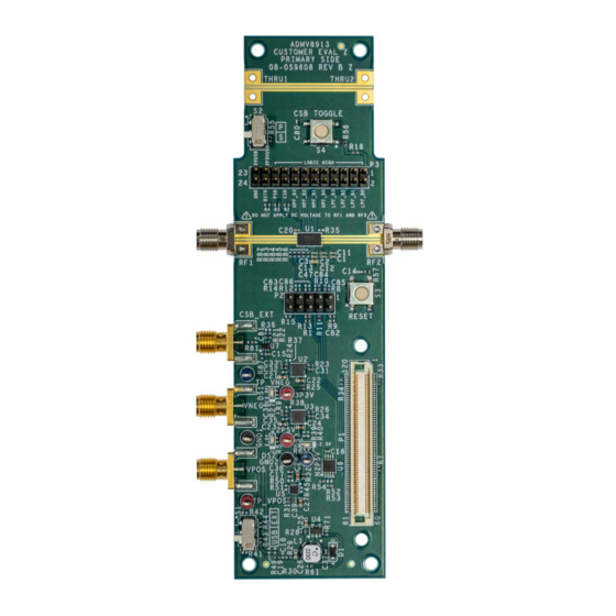
EVALUATION BOARD PHOTOGRAPH
Fully featured evaluation board for the ADMV8913
On-board
SDP-S
connector for the SPI
Evaluation using on-board LDO regulators powered by the USB
ACE
software interface for SPI control
EQUIPMENT NEEDED
Network analyzer
Windows® PC
USB cable
EVAL-SDP-CS1Z
(SDP-S) controller board
DOCUMENTS NEEDED
ADMV8913 data sheet
SOFTWARE NEEDED
ACE software
GENERAL DESCRIPTION
The ADMV8913-EVALZ is available for evaluating the
ADMV8913 digitally tunable, high-pass filter (HPF) and low-
pass filter (LPF). The ADMV8913-EVALZ incorporates the
ADMV8913 chip, as well as a negative voltage generator, low
dropout (LDO) regulators, and an interface to the EVAL-SDP-
CS1Z (SDP-S) system demonstration platform (SDP) to allow
simple and efficient evaluation. The negative voltage generator
and LDO regulators allow the ADMV8913 to be powered by
either the 5 V USB supply voltage from the PC via the SDP-S
or by using two external power supplies.
The ADMV8913 is a fully monolithic microwave integrated
circuit (MMIC) that features a digitally selectable frequency
of operation. The chip has an integrated HPF followed by an
integrated LPF that allows a pass-band response within the X band
frequency range. The chip can be programmed using either the
parallel logic interface or a 4-wire serial port interface (SPI). The
SDP-S controller allows the user to interface with the ADMV8913
SPI through the Analog Devices, Inc., Analysis | Control |
Evaluation (ACE) software.
For full details on the ADMV8913, see the ADMV8913 data
sheet, which must be consulted in conjunction with this user
guide when using the ADMV8913-EVALZ.
Figure 1.
PLEASE SEE THE LAST PAGE FOR AN IMPORTANT
Rev. 0 | Page 1 of 17
WARNING AND LEGAL TERMS AND CONDITIONS.
Arrow.com.
Downloaded from
Advertisement
Table of Contents

Related Manuals for Analog Devices ADMV8913-EVALZ


Summary of Contents for Analog Devices ADMV8913-EVALZ
-
Page 1: Features
4-wire serial port interface (SPI). The SDP-S controller allows the user to interface with the ADMV8913 SPI through the Analog Devices, Inc., Analysis | Control | Evaluation (ACE) software. For full details on the ADMV8913, see the ADMV8913 data sheet, which must be consulted in conjunction with this user guide when using the ADMV8913-EVALZ. -
Page 2: Table Of Contents
UG-1952 ADMV8913-EVALZ Evaluation Board User Guide TABLE OF CONTENTS Features ....................1 ADMV8913-EVALZ Quick Start ..........9 Equipment Needed ................1 Network Analyzer Settings ............9 Documents Needed ................1 CSV Files ..................10 ... -
Page 3: Evaluation Board Hardware
To power the ADMV8913-EVALZ using the 5 V USB supply, P3 connector and then latching in that data by pressing the CSB slide the S1 switch down (as shown in Figure 2) to power the Toggle S4 button. -
Page 4: Evaluation Board Software
Attached Hardware section of the Start tab PLUG-INS, AND DRIVERS when the ACE software is running. (see Figure 4). The ADMV8913-EVALZ uses Analog Devices ACE software. For instructions on how to install and use the ACE software, go to the ACE software page. -
Page 5: Plug-In Overview
Evaluation Board User Guide UG-1952 PLUG-IN OVERVIEW When the ADMV8913-EVALZ is connected to the PC, the ADMV8913 Board appears in the Attached Hardware section of the Start tab. Double click the ADMV8913 Board plug-in to open two tabs, the ADMV8913 Board plug-in view (see Figure 5) and the ADMV8913 chip plug-in (see Figure 6), respectively. -
Page 6: Plug-In Details
Label Function Use the CONFIGURATION section to initialize the ADMV8913-EVALZ. Load Settings from CSV: click the … button to select which CSV file to load into the CONFIGURATION section. Check to Load Settings: once a file has been selected, select this check box to load the CSV file contents into the CONFIGURATION section. - Page 7 LUT. If an external waveform generator is connected to the CSB_EXT port on the ADMV8913-EVALZ, the CSB_AUX pin has no effect, and the CSB_EXT port takes precedence. Click Proceed to Memory Map to open the ADMV8913 Memory Map (see Figure 8).
- Page 8 UG-1952 ADMV8913-EVALZ Evaluation Board User Guide Figure 8. ADMV8913 Memory Map in the Software Rev. 0 | Page 8 of 17 Arrow.com. Arrow.com. Arrow.com. Arrow.com. Arrow.com. Arrow.com. Arrow.com. Arrow.com. Downloaded from Downloaded from Downloaded from Downloaded from Downloaded from Downloaded from...
-
Page 9: Performing Evaluation
UG-1952 PERFORMING EVALUATION ADMV8913-EVALZ QUICK START To set up the ADMV8913-EVALZ, take the following steps: Connect the RF1 and RF2 ports to a network analyzer (or a similar instrument). Typically, RF1 and RF2 are connected to Port 1 and Port 2 on the network analyzer, as shown in Figure 2. -
Page 10: Csv Files
0 Ω resistors (R25 • Programs Register 0x000 to 0x3C to enable the SDO pin on and R32) from the ADMV8913-EVALZ, and then applying each the ADMV8913 and to allow SPI streaming with Endian voltage independently by using the corresponding test points. -
Page 11: Plug-In Spi Register Controller
PARALLEL MODE Determine if Register 0x000 is not set to 0x3C. The ADMV8913-EVALZ can be configured to operate the If Step 1 is true, set Register 0x000 to 0x3C to enable the ADMV8913 chip in parallel mode. Slide the S2 switch up SDO pin on the ADMV8913 and allow SPI streaming with for parallel mode. -
Page 12: Evaluation Board Schematics And Artwork
FOR 10MILTHK CORE LAYER USE 33Ω 49.9Ω 142-0701-851 CSB_EXT 0Ω CSB_U1 3P3VUSB 10pF 0Ω 0.1µF ADG749BKSZ 0Ω Figure 10. ADMV8913-EVALZ Schematic, Page 1 Rev. 0 | Page 12 of 17 Arrow.com. Arrow.com. Arrow.com. Arrow.com. Arrow.com. Arrow.com. Arrow.com. Arrow.com. Arrow.com. Arrow.com. Arrow.com. - Page 13 10µF 0.1µF 0.1µF 29.4kΩ C0603 0Ω V IN REG_POS_IN SHDN 10µF C0402 24.9kΩ 1µF BAT54H,115 Figure 11. ADMV8913-EVALZ Schematic, Page 2 Rev. 0 | Page 13 of 17 Arrow.com. Arrow.com. Arrow.com. Arrow.com. Arrow.com. Arrow.com. Arrow.com. Arrow.com. Arrow.com. Arrow.com. Arrow.com. Arrow.com.
- Page 14 UG-1952 ADMV8913-EVALZ Evaluation Board User Guide Figure 12. ADMV8913-EVALZ Layer 1 Figure 13. ADMV8913-EVALZ Layer 2 Rev. 0 | Page 14 of 17 Arrow.com. Arrow.com. Arrow.com. Arrow.com. Arrow.com. Arrow.com. Arrow.com. Arrow.com. Arrow.com. Arrow.com. Arrow.com. Arrow.com. Arrow.com. Arrow.com. Downloaded from Downloaded from...
- Page 15 ADMV8913-EVALZ Evaluation Board User Guide UG-1952 Figure 14. ADMV8913-EVALZ Layer 3 Figure 15. ADMV8913-EVALZ Layer 4 Rev. 0 | Page 15 of 17 Arrow.com. Arrow.com. Arrow.com. Arrow.com. Arrow.com. Arrow.com. Arrow.com. Arrow.com. Arrow.com. Arrow.com. Arrow.com. Arrow.com. Arrow.com. Arrow.com. Arrow.com. Downloaded from...
-
Page 16: Ordering Information
UG-1952 ADMV8913-EVALZ Evaluation Board User Guide ORDERING INFORMATION BILL OF MATERIALS Table 2. ADMV8913-EVALZ Quantity Reference Designator Description Manufacturer Part Number 2P5V, 3P3V, TP_VPOS Test points, red Components Corporation TP-104-01-02 GND1, GND2 Test points, black Components Corporation TP-104-01-00 N2P5V, TP_VNEG... - Page 17 By using the evaluation board discussed herein (together with any tools, components documentation or support materials, the “Evaluation Board”), you are agreeing to be bound by the terms and conditions set forth below (“Agreement”) unless you have purchased the Evaluation Board, in which case the Analog Devices Standard Terms and Conditions of Sale shall govern. Do not use the Evaluation Board until you have read and agreed to the Agreement.
Need help?
Do you have a question about the ADMV8913-EVALZ and is the answer not in the manual?
Questions and answers