Advertisement
Quick Links
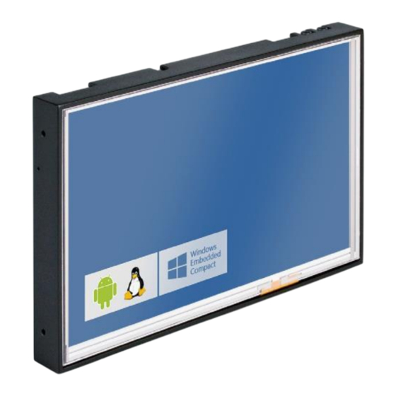
i-PAN7
Documentation version 2.0
1 INTRODUCTION
The i-PAN7 is a flat panel ready to go solution, which can be easily integrated in customer devices. It
consists of a 7" touch-display combined with a thin metal hous- ing including most peripherals needed
by todays typical panel-applications. To make it easy for customers to attach their own peripherals or to
put connectors on a desired place in a product, the i-PAN7 additionally has extensions connectors.
The device offers the following features:
WVGA (800 x 480) 7" TFT-display with resistive or capacitive touch
Small metal housing with mounting possibility
Single Power supply, 7...24 Volt range
SDIO/SD/MMC card socket
USB Host
3-axis accelerometer
2,6W stereo speaker output
20 bit stereo headphone output
Mic input (mono) for electret-capacitor microphones
Analog video/camera input via mini BNC
Quad-band GSM/GPRS or UMTS modem
GPS receiver
Realtime clock
Version 2.0
i-PAN7
1 of 14
Advertisement

Subscribe to Our Youtube Channel
Related Manuals for Seco i-PAN7


Summary of Contents for Seco i-PAN7
- Page 1 Documentation version 2.0 1 INTRODUCTION The i-PAN7 is a flat panel ready to go solution, which can be easily integrated in customer devices. It consists of a 7" touch-display combined with a thin metal hous- ing including most peripherals needed by todays typical panel-applications.
- Page 2 IrDA Programmable input and output pins (CPLD) CAN bus ▪ Please do not use the card socket on i-PAN7 and Connector Board at same time! This can cause data loss on the memory card! ▪ level converter: 24V ▪ level converter: 24V ▪...
- Page 3 COM1 FF_UART COM2 BT_UART/RS485* Trizeps IV-M, IV-WL, V, VI, VII External antenna COM3_ ST_UART* Audio Headphone Microphone Acceleration 3 * ADC 10 or 12 bit Programmable I/O͚ s IrDa Extension CAN bus connector 2 Version 2.0 i-PAN7 3 of 14...
- Page 4 Samtec - FTSH Series, 80 pin optional Power in Phoenix - MSTBA2,5/2-G-5.08 Ethernet RJ45 Display Connector LVDS 40pin 0.5mm pitch bottom contact J32/33/34 Touch Connector for 10“ LVDS SMD ZIF, TC 0.5mm Pitch 5-lead Version 2.0 i-PAN7 4 of 14...
-
Page 5: Extension Connectors
The extension connectors offer a possibility to extend the functionality of the i-PAN7 to a custom specific requirement. All signals are listed in the following tables 3 and 4. Figure 3 shows how to identify the pins of the dual row type connec- tors. The bottom row is the A-row and the upper is the B-row. - Page 6 USB Slave USB_SL_D+ USB_SL_D- USB Slave COM2_CTS_V24 COM2_RTS_V24 COM2 COM2_TXD_485H COM2_RXD_485L COM2/RS485 FF_RTS_V24X FF_DTR_V24X COM1 FF_DSR_V24X FF_TXD_V24X COM1 FF_RXD_V24X FF_CTS_V24X COM1 FF_RI_V24X FF_DCD_V24X COM1 RXD_2 TXD_2 COM3 V_SUP_N V_SUP_P External Power V_SUP_N V_SUP_P External Power Version 2.0 i-PAN7 6 of 14...
- Page 7 OUT5 CPLD I/O OUT4 CPLD I/O OUT3 CPLD I/O OUT2 CPLD I/O OUT1 CPLD I/O OUT0 CPLD I/O IRDA_MODE IRDA_SD IrDa +3V3 +3V3 max. 500 mA CAN_L CAN_H CAN Bus GND_ISO GND_ISO CAN Bus Version 2.0 i-PAN7 7 of 14...
- Page 8 BL_PWM PWM backlight CPLD dual color LED, low: red, high: yellow GPIO GPIO GPIO GPIO Signal name Trizeps IV Trizeps V Trizeps VI Trizeps VII Function / location GP00 not usable GPIO, J2-A26 Version 2.0 i-PAN7 8 of 14...
-
Page 9: Power Supply
4 POWER SUPPLY The i-PAN7 needs a nominal power supply of 12 Volt. The device will work stable in a power range of 7 ... 24 Volt. Applying a voltage more than 24 Volt will damage electronic components. Usually connector J13 is equiped. The polarity is shown in figure 4. - Page 10 5 OUTLINES PCB outlines top side FIGURE 5. PCB outlines top side Version 2.0 i-PAN7 10 of 14...
- Page 11 PCB outlines bottom side FIGURE 6. PCB outlines bottom side Version 2.0 i-PAN7 11 of 14...
-
Page 12: Solder Bridges
5.2.1 Solder Bridges There are several solder-bridges on the backside of the i-PAN7, which modify how some interfaces of the panel will function. Solder Bridge Description LB5, LB16 Route USB-host port 1 to J30, J32,J33,J34. Trizeps IV/V and Trizeps VI/VII use different Ethernet-Phys. - Page 13 The outlines of the device including the plastic housing are: 169 mm x 108 mm x 17 mm Weigt (typ): 340 g 6 MOUNTING The housing of i-PAN7 is a small and thin metal frame. It has four mounting holes for M4 screws. Picture 7 shows the frame. FIGURE 7.
-
Page 14: Revision History
Added 5.2.1 Solder Bridges 2022.11.18 Update new CI SECO Northern Europe GmbH Schlachthofstraße 20 21079 Hamburg E-Mail: north@seco.com https://north.seco.com All rights reserved. Products subject to technical changes, improvements and misprints. © 2022 SECO Northern Europe GmbH Version 2.0 i-PAN7 14 of 14...
Need help?
Do you have a question about the i-PAN7 and is the answer not in the manual?
Questions and answers