Table of Contents
Advertisement
Quick Links
MC56F80000-EVKUM
MC56F80000-EVK Board User Manual
Rev. 1 — 14 December 2022
Document information
Information
Content
Keywords
MC56F80000-EVK, MC56F80748, MC56F80xxx
Abstract
The NXP MC56F80000 Evaluation Kit board (MC56F80000-EVK) is a simple,
yet sophisticated design featuring the MC56F80748 digital signal controller
(DSC), a device that combines the processing power of a digital signal
processor (DSP) and the functionality of a microcontroller (MCU).
User manual
Advertisement
Table of Contents

Subscribe to Our Youtube Channel
Related Manuals for NXP Semiconductors MC56F80000-EVKUM


Summary of Contents for NXP Semiconductors MC56F80000-EVKUM
- Page 1 MC56F80000-EVKUM MC56F80000-EVK Board User Manual Rev. 1 — 14 December 2022 User manual Document information Information Content Keywords MC56F80000-EVK, MC56F80748, MC56F80xxx Abstract The NXP MC56F80000 Evaluation Kit board (MC56F80000-EVK) is a simple, yet sophisticated design featuring the MC56F80748 digital signal controller (DSC), a device that combines the processing power of a digital signal processor (DSP) and the functionality of a microcontroller (MCU).
-
Page 2: Overview
MC56F80000-EVKUM NXP Semiconductors MC56F80000-EVK Board User Manual Overview The NXP MC56F80000 Evaluation Kit board (MC56F80000-EVK) is a simple, yet sophisticated design featuring the MC56F80748 digital signal controller (DSC), a device that combines the processing power of a digital signal processor (DSP) and the functionality of a microcontroller (MCU). -
Page 3: Related Documentation
MC56F80000-EVKUM NXP Semiconductors MC56F80000-EVK Board User Manual Table 1. Acronyms and abbreviations ...continued Term Description OPAMP Operational amplifier OpenSDA Open-standard serial and debug adapter Programmable gain amplifier Pulse width modulation QSPI Quadruple serial peripheral interface Software development kit Serial peripheral interface... -
Page 4: Block Diagram
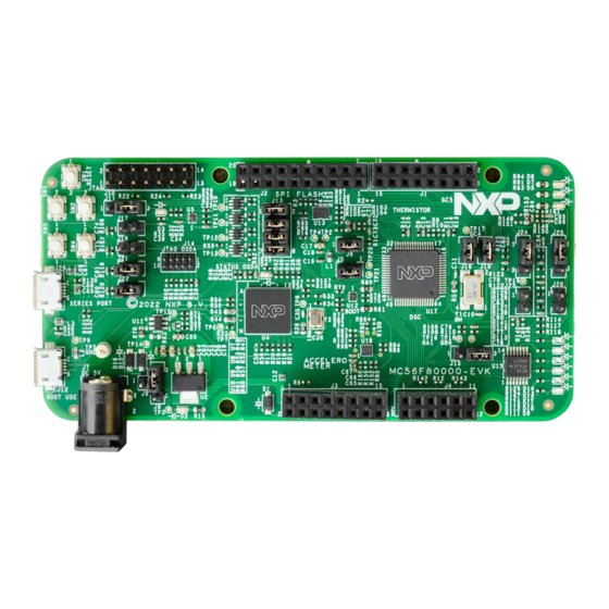
MC56F80000-EVKUM NXP Semiconductors MC56F80000-EVK Board User Manual Table 3. Hardware kit contents Item Quantity MC56F80000-EVK board hardware assembly USB Type A to micro USB Type B cable, 1 m MC56F80000-EVK Quick Start Guide 1.4 Block diagram The figure below shows the MC56F80000-EVK block diagram. - Page 5 MC56F80000-EVKUM NXP Semiconductors MC56F80000-EVK Board User Manual MC56F80748 DSC Figure 2. MC56F80000-EVK top view The following figure shows the onboard connectors on MC56F80000-EVK. JTAG connector I/O header I/O header for MC56F80748 OpenSDA/K26 JTAG USB virtual serial port (CP210x) / external 5 V power connector...
-
Page 6: Board Features
MC56F80000-EVKUM NXP Semiconductors MC56F80000-EVK Board User Manual The following figure shows the Jumpers, LEDs, and push buttons on MC56F80000-EVK. J16 J19 J9 J8 Figure 4. MC56F80000-EVK jumpers, LEDs, and push buttons 1.6 Board features The following table lists the features of MC56F80000-EVK. -
Page 7: Push-Button Switches
MC56F80000-EVKUM NXP Semiconductors MC56F80000-EVK Board User Manual Table 4. MC56F80000-EVK features ...continued MC56F80000-EVK Processor feature used Description feature 3-axis low-g accelerometer Low-power inter-integrated • Supports NXP FXLS8974CF accelerometer for motion circuit (LPI2C) module sensing • Device supports both high-performance and low-power operating modes •... -
Page 8: Connectors
MC56F80000-EVKUM NXP Semiconductors MC56F80000-EVK Board User Manual Table 5. Push buttons ...continued Part Switch Description identifier type Push SW3 connects to GPIOE7 when jumper J18 is shorted. Pressing SW3 gives a low level on button GPIOE7, otherwise, it is a high level on GPIOE7. - Page 9 MC56F80000-EVKUM NXP Semiconductors MC56F80000-EVK Board User Manual Table 7. MC56F80000-EVK jumpers Part Jumper Description Jumper settings identifier type 1x2-pin Shorted pin 1-2 (default setting): Connect VDD to DSC digital power header supply VDD_MCU 1x2-pin VDDA Shorted pin 1-2 (default setting): Connect VDDA to DSC analog power...
-
Page 10: Leds
MC56F80000-EVKUM NXP Semiconductors MC56F80000-EVK Board User Manual Table 7. MC56F80000-EVK jumpers ...continued Part Jumper Description Jumper settings identifier type 1x2-pin • Open: Disconnect SW4 button from MC56F80748 GPIOF8 header • Shorted (default setting): Connect SW4 button to MC56F80748 GPIOF8 1x2-pin • Open: Disconnect SW5 button from MC56F80748 GPIOC13 header •... -
Page 11: Mc56F80000-Evk Functional Description
MC56F80000-EVKUM NXP Semiconductors MC56F80000-EVK Board User Manual Table 8. MC56F80000-EVK LEDs ...continued Part identifier LED color LED name Description (When LED in ON) Yellow/Green PWM LED2 Indicates that GPIOE2/PWMA_1B function is enabled and PWM signal is outputted. A high level turns on the LED. -
Page 12: Power Distribution
MC56F80000-EVKUM NXP Semiconductors MC56F80000-EVK Board User Manual Table 9. 5 V power sources Part identifier Device/Power source Output power supply Description 5 V DC power jack PWR_IN OpenSDA micro- P5V0_OSDA • Source of P5V0_OSDA_OUT AB USB connector • Supplies power to the power switch, MIC2005-0. -
Page 13: Clocking
MC56F80000-EVKUM NXP Semiconductors MC56F80000-EVK Board User Manual Table 10. 3.3 V power nodes on MC56F80000-EVK Part Device Power supply Description identifier voltage LD1117 VDD (3.3 V) • Source of VDD_MCU and VDDA • Power supply for voltage level translators, NTSX2102GU8H (U5), 74LVC1T45GW (U7, U8, U9, U10), and NTSX2102GU8H (U12) •... -
Page 14: 3-Axis Digital Sensor
MC56F80000-EVKUM NXP Semiconductors MC56F80000-EVK Board User Manual 2.3 3-axis digital sensor The MC56F80000-EVK board supports motion sensing using NXP FXLS8974CFR3 accelerometer. FXLS8974CFR3 is a compact 3-axis MEMS accelerometer designed for use in applications that require ultra-low-power wake-up on motion. FXLS8974CFR3 is connected to MC56F80748 through I2C interface, LPI2C. The INTF_SEL pin of FXLS8974CFR3 has been connected to GND, so that I2C interface mode is selected for this device. -
Page 15: Spi Flash Interface
MC56F80000-EVKUM NXP Semiconductors MC56F80000-EVK Board User Manual 2.4 SPI Flash interface The MC56F80748 supports one queued serial peripheral interface (QSPI) controller that provides: • Maximum of 25 Mbit/s baud rate • Full-duplex operation • Master and slave modes The QSPI controller signals are multiplexed with the GPIO (Group C) pin signals. -
Page 16: Pwm Interface
MC56F80000-EVKUM NXP Semiconductors MC56F80000-EVK Board User Manual • Resistor divider circuit 1 – Thermistor RT1 is between THER_A and THER_B – Supports temperature from 90 °C to -20 °C – THER_A is connected to the GPIOA6 (ANA6) pin of MC56F80748 –... - Page 17 MC56F80000-EVKUM NXP Semiconductors MC56F80000-EVK Board User Manual is a DC signal, which can be used as ADC/CMP input signal through GPIOB6 (ANB6+CMPB_IN1) and GPIOB7 (ANB7+CMPB_IN2). • OPAMP test configuration – PGA mode test When the pin 1 and pin 2 of J15 are connected, J16 is unconnected and J19 is connected, the PGA mode for OPAMP can be tested.
-
Page 18: Opamp Test Circuit
MC56F80000-EVKUM NXP Semiconductors MC56F80000-EVK Board User Manual 2.7 OPAMP test circuit The OPAMP test circuit is designed to use the DSC internal OPAMPs together with the phase current sensing circuit of motor power stage board (FRDM-MC-LVPMSM). The FRDM-MC-LVPMSM board is connected with the EVK board through Arduino interface. -
Page 19: Opensda
MC56F80000-EVKUM NXP Semiconductors MC56F80000-EVK Board User Manual R129 GB0_IN Figure 16. Equivalent circuit for phase B current sensing — with external OPAMP • With DSC internal OPAMP In phase A current sensing circuit, when the DSC internal OPAMP is used for current sensing, the jumpers configuration is described as follows. -
Page 20: Input/Output Headers
MC56F80000-EVKUM NXP Semiconductors MC56F80000-EVK Board User Manual The OpenSDA circuit is based on the NXP Kinetis K26 family microcontroller (MK26FN2M0VMI18) with 2 MB of embedded flash and an integrated USB controller. OpenSDA comes preloaded with the firmware, which provides a debug protocol interface and a virtual serial port interface. -
Page 21: Arduino Compatibility
MC56F80000-EVKUM NXP Semiconductors MC56F80000-EVK Board User Manual Table 16. J1 (2x8-pin) connector pinout Signal Signal GPIOC12 (RXD1) Not connected GPIOC11 (TXD1 GPIOC6 (ENC_I/XB_IN3) GPIOF5 (GF5/XB_OUT9) Not connected GPIOF4(GF4/XB_OUT8) Not connected GPIOC4/OPA_OUT Not connected GPIOC15 (ANA4c) Not connected GPIOC7 (SS0/XB_OUT6) Not connected... - Page 22 MC56F80000-EVKUM NXP Semiconductors MC56F80000-EVK Board User Manual • OpenSDA circuit — The OpenSDA microcontroller MK26FN2M0VMI18 provides a virtual COM between the host computer and MC56F80748 through USB port (J12) by using SCI0 on MC56F80748. The MC56F80748 features two high-speed queued serial communication interface (QSCI) modules (SCI0 and SCI1) with LIN slave functionality.
-
Page 23: Debug
MC56F80000-EVKUM NXP Semiconductors MC56F80000-EVK Board User Manual VDD_2102 R130 4.7K 0.1 µF 4.7 µF P5V_USB2 VBUS SUSPEND VBUS SUSPEND USB_- D RI/CLK USB_+D TP20 R131 R132 VREGIN TXD1 CHREN 0 DNP R157 GC11 CHR0 0.1 µF CHR1 RXD1 4.7 µF... -
Page 24: Opensda Debug Interface
MC56F80000-EVKUM NXP Semiconductors MC56F80000-EVK Board User Manual Table 21. JTAG header (J10) pinout ...continued Pin number Signal name Description Ground Not connected Not connected GPIOD4/RESET Reset signal GPIOD3/TMS TAP machine state Power supply Not connected Power supply Not connected 2.12.2 OpenSDA debug interface The MC56F80000-EVK board supports onboard OpenSDA debugging. -
Page 25: Legal Information
NXP Semiconductors. In the event that customer uses the product for design-in and use in In no event shall NXP Semiconductors be liable for any indirect, incidental, automotive applications to automotive specifications and standards, punitive, special or consequential damages (including - without limitation - customer (a) shall use the product without NXP Semiconductors’... -
Page 26: Table Of Contents
Please be aware that important notices concerning this document and the product(s) described herein, have been included in section 'Legal information'. © 2022 NXP B.V. All rights reserved. For more information, please visit: http://www.nxp.com Date of release: 14 December 2022 Document identifier: MC56F80000-EVKUM...
Need help?
Do you have a question about the MC56F80000-EVKUM and is the answer not in the manual?
Questions and answers