Table of Contents
Advertisement
Quick Links
UM12036
MCX-N9XX-EVK Board User Manual
Rev. 1 — 20 January 2024
Document information
Information
Keywords
Abstract
Content
MCX-N9XX-EVK, UM12036, MCX N94x
The NXP MCX N9XX Evaluation Kit (MCX-N9XX-EVK) board is a full-featured evaluation and
development board for application prototyping and demonstration of the MCX N94x family of
devices. This document describes the hardware for the MCX-N9XX-EVK development board.
User manual
Advertisement
Table of Contents

Subscribe to Our Youtube Channel
Related Manuals for NXP Semiconductors MCX-N9 EVK Series


Summary of Contents for NXP Semiconductors MCX-N9 EVK Series
- Page 1 UM12036 MCX-N9XX-EVK Board User Manual Rev. 1 — 20 January 2024 User manual Document information Information Content Keywords MCX-N9XX-EVK, UM12036, MCX N94x Abstract The NXP MCX N9XX Evaluation Kit (MCX-N9XX-EVK) board is a full-featured evaluation and development board for application prototyping and demonstration of the MCX N94x family of devices.
-
Page 2: Mcx-N9Xx-Evk Overview
UM12036 NXP Semiconductors MCX-N9XX-EVK Board User Manual 1 MCX-N9XX-EVK overview The NXP MCX N9XX Evaluation Kit (MCX-N9XX-EVK) board is a full-featured evaluation and development board for application prototyping and demonstration of the MCX N94x family of devices. The MCX N94X integrates a dual Arm Cortex-M33 MCU and a neural processing unit (NPU) into a single package. -
Page 3: Board Features
UM12036 NXP Semiconductors MCX-N9XX-EVK Board User Manual 1.2 Board features Table 1 describes the features of the MCX-N9XX-EVK board. Table 1. MCX-N9XX-EVK features Board feature Target MCU features used Description MCX N94x MCU The MCX N94x is based on dual high-performance Arm... -
Page 4: Board Kit Contents
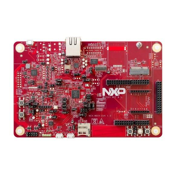
UM12036 NXP Semiconductors MCX-N9XX-EVK Board User Manual Table 1. MCX-N9XX-EVK features ...continued Board feature Target MCU features used Description Debug • Onboard MCU-Link debug probe with CMSIS-DAP and SEGGER J-Link protocol options. It can connect to the target MCU through a USB-to-UART, USB-to-SPI, or USB- to-I2C bridge. - Page 5 UM12036 NXP Semiconductors MCX-N9XX-EVK Board User Manual Figure 3 shows the top-side view of the MCX-N9XX-EVK board, with connectors, push buttons, and LEDs highlighted. (10 / 100 Mbit/s RJ45) (Debug and trace) (MCU-Link USB) (External Flash) (MCU-Link SWD) (MCU-Link (M.2)
-
Page 6: Connectors
UM12036 NXP Semiconductors MCX-N9XX-EVK Board User Manual JP11 JP12 JP16 (DNP) (DNP) JP13 JP15 JP20 (DNP) JP10 JP14 (DNP) JP23 J17 J18 JP18 JP1 (DNP) JP2 (DNP) JP3 (DNP) JP7 JP8 (DNP) JP21 JP17 JP22 JP19 JP24 JP35 JP28 JP25... -
Page 7: Jumpers
UM12036 NXP Semiconductors MCX-N9XX-EVK Board User Manual Table 2. MCX-N9XX-EVK connectors ...continued Part Connector type Description Reference section identifier RJ45 connector Shielded RJ45 connector jack with magnetic Section 2.6 built-in J9 (DNP) 2 x 14 pin header To connect external flash daughter card Section 2.5... - Page 8 UM12036 NXP Semiconductors MCX-N9XX-EVK Board User Manual Table 3. MCX-N9XX-EVK jumpers ...continued Part Jumper type Description Reference section identifier 1x2 pin header • Pin 1-2 open: Disconnects the P3V3 supply from the Section 2.6 LAN8741 Ethernet PHY circuit • Pin 1-2 shorted (default setting): Connects the P3V3...
- Page 9 UM12036 NXP Semiconductors MCX-N9XX-EVK Board User Manual Table 3. MCX-N9XX-EVK jumpers ...continued Part Jumper type Description Reference section identifier Note: Default setting for LDO_CORE disable case. JP19 1x2 pin header • Open (default setting): Enables serial port connection Section 3.8 (VCOM) between MCU-Link and the target MCU (connected through pins P1_8 and P1_9) •...
- Page 10 UM12036 NXP Semiconductors MCX-N9XX-EVK Board User Manual Table 3. MCX-N9XX-EVK jumpers ...continued Part Jumper type Description Reference section identifier • Pin 5-6 shorted: VDD_DCDC is pulled down to GND Note: In DC-DC bypass mode, open pin 1-2 and short pins 3-4 and 5-6.
- Page 11 UM12036 NXP Semiconductors MCX-N9XX-EVK Board User Manual Table 3. MCX-N9XX-EVK jumpers ...continued Part Jumper type Description Reference section identifier MCX-N9XX-EVK schematic JP43 1x3 pin header PMIC reset Section 2.1 • Pin 1-2 shorted (default setting): PMIC reset is supported through the SW5 push button •...
-
Page 12: Push Buttons
UM12036 NXP Semiconductors MCX-N9XX-EVK Board User Manual 1.7 Push buttons Tactile buttons are populated on the MCX-N9XX-EVK board for human machine interaction (HMI). Each of the SW[4:2] buttons has a 0.1 µF bypass capacitor for debouncing and pads for external pull-up resistors, if desired. -
Page 13: Leds
UM12036 NXP Semiconductors MCX-N9XX-EVK Board User Manual 1.8 LEDs Table 5 describes the MCX-N9XX-EVK light-emitting diodes (LEDs) that correspond to the target MCU. The board also has some MCU-Link-specific LEDs, which are described in Section 3.11. The LEDs are shown in Figure Table 5. MCX-N9XX-EVK LEDs... - Page 14 UM12036 NXP Semiconductors MCX-N9XX-EVK Board User Manual The P5V0 supply is an input power supply for the onboard PCA9420 PMIC (U2) and ADM172 3.3 V regulator (U54), which provides secondary power supplies. The P5V0 supply also powers up the energy monitoring analog circuits, FS / HS USB VBUS controllers, and CAN driver.
- Page 15 UM12036 NXP Semiconductors MCX-N9XX-EVK Board User Manual Figure 7. MCX-N9XX-EVK 5 V power source selection 3.3 V power sources and selection The following table describes the 3.3 V input power sources and their output power supplies. Table 7. P3V3 power sources Part identifier...
- Page 16 UM12036 NXP Semiconductors MCX-N9XX-EVK Board User Manual Table 7. P3V3 power sources ...continued Part identifier Device / power source Output power supply Description • One of the sources for VDD_P3 supply through the JP15 jumper. For details, see Section 1.6 • One of the sources for VDD_P4 supply through the JP45 jumper.
- Page 17 UM12036 NXP Semiconductors MCX-N9XX-EVK Board User Manual Table 8. P1V8 power sources ...continued Part identifier Device / power source Output power supply Description • One of the sources for th eVDD_P3 supply through the JP15 jumper. For details, see Section 1.6 •...
- Page 18 UM12036 NXP Semiconductors MCX-N9XX-EVK Board User Manual Figure 10. P1V1 source selection Once the main power configurations are set, the target MCU power configurations must be made. The MCU power is configured by a network of jumpers as shown in Figure These jumpers provide access to insert ammeters in all the supplies connecting to the MCX N94X device.
-
Page 19: Power Supply Configuration
UM12036 NXP Semiconductors MCX-N9XX-EVK Board User Manual SHORTING HEADER ON BOTTOM LAYER Figure 11. Power configuration jumpers The MCX-N9XX-EVK board supports current measurement for board power supplies through the onboard MCU-Link debug probe. For more details, see Section 3.10. 2.1.1 Power supply configuration •... -
Page 20: Dc-Dc Inductor
UM12036 NXP Semiconductors MCX-N9XX-EVK Board User Manual Table 10. MCX-N9XX-EVK default power supply configuration Description JP38 JP27 JP35 JP18 JP36 JP31 JP37 JP47 JP15 JP45 Dual IO, 3.3 V and 1.8 V Changing JP15 to 3.3 V requires cutting a cut trace at the bottom of the board and installing a header. If this setting is done, care must be taken to disconnect or remove the onboard flash device, as this device is a 1.8 V only device. -
Page 21: Clocks
UM12036 NXP Semiconductors MCX-N9XX-EVK Board User Manual Figure 12. DC-DC inductor circuit diagram Choosing the right DC-DC inductor for your target board is important. While selecting a DC-DC inductor, look for the following specifications: • Inductor value: 1.5 µH • ESR: < 0.3 Ω... -
Page 22: Usb Interface
UM12036 NXP Semiconductors MCX-N9XX-EVK Board User Manual Table 13. MCX-N9XX-EVK clocks ...continued Clock Clock Destination Description generator frequency • Port 5 pin 0 (EXTAL32K) of target • Internal load capacitors provide the entire MCU MCX N94X crystal load capacitance. • To measure the 32.768 kHz oscillator frequency, enable the RTC_CLKOUT signal to be available on the TAMPER1 pin. -
Page 23: Sd Card Interface
UM12036 NXP Semiconductors MCX-N9XX-EVK Board User Manual VBUS control Figure 14. FS USB circuit diagram HS USB interface On the MCX-N9XX-EVK board, the USB1_DM and USB1_DP signals from the MCX N94X MCU connect to the onboard USB connector (J27) directly through a common mode choke. The common mode choke is included for noise suppression on the DM / DP signals, however, pads are included to install bypass resistors for testing choke-less configurations. - Page 24 UM12036 NXP Semiconductors MCX-N9XX-EVK Board User Manual Figure 16. Micro SD card connector circuit The Port P2_[7:1] lines that are used for SDHC interface signals are also shared with the M.2 connector (J12) signals and the PWM signals on the Arduino compatible header (J3). Zero-ohm onboard resistors are used to allow the selection of signals between the SDHC card slot or the M.2 connector.
-
Page 25: Flash Memory Interface
UM12036 NXP Semiconductors MCX-N9XX-EVK Board User Manual 2.5 Flash memory interface The target MCU (MCX N94X) features one Flexible Serial Peripheral Interface (FlexSPI) controller, which can support an external memory. On the MCX-N9XX-EVK board, one Quad SPI memory is provided. The flash memory VCC (VDD_FLASH) is supplied by the P1V8 rail through the JP15 jumper. - Page 26 UM12036 NXP Semiconductors MCX-N9XX-EVK Board User Manual Figure 19. Resistors configuration Table 16 describes the zero-ohm resistors configuration to select onboard flash memory or other board components on the flash interface lines. Table 16. Zero-ohm resistors configuration Port[pin] / Resistor Resistor configuration...
-
Page 27: Ethernet Interface
UM12036 NXP Semiconductors MCX-N9XX-EVK Board User Manual Table 16. Zero-ohm resistors configuration ...continued Port[pin] / Resistor Resistor configuration Description Signal P3_8 R901 For flash data signals P3_9 R902 P3_10 R903 P3_11 R904 P3_12 R939, R957, • R939 Populated (default setting): Connects the signals... -
Page 28: Accelerometer Sensor Interface
UM12036 NXP Semiconductors MCX-N9XX-EVK Board User Manual Table 17. Ethernet interface devices Part identifier Part name and Manufacturer Description Würth Elektronik 7499211121A Shielded RJ45 connector jack with magnetic built-in to connect to an Ethernet cable Microchip Technology LAN8741 Single-chip 10 /100 Mbit/s RMII Ethernet PHY is compliant with IEEE802.3/802.3u (Fast Ethernet), ISO 802-3/IEEE 802.3 (10... -
Page 29: I3C Interface
UM12036 NXP Semiconductors MCX-N9XX-EVK Board User Manual Figure 20. FXLS8964AF sensor circuit 2.8 I3C interface The MCX-N9XX-EVK includes one P3T1755 digital temperature sensor to demonstrate the I3C capabilities of the target MCU. This device allows for 32 I3C provisional IDs, supports the fully operating voltage of the board (1.71 V - 3.6 V), programmable overtemperature alerts, 12b resolution, and has an accuracy of ±... - Page 30 UM12036 NXP Semiconductors MCX-N9XX-EVK Board User Manual extended message frames and long payloads. The target MCU (MCX N94X) supports two CAN (w/wo FD) controllers (CAN0 to CAN1). On MCX-N9XX-EVK, only the CAN0 controller is used. The CAN0 controller connects to a 4-pin CAN header through a CAN transceiver.
-
Page 31: Visible Light Sensor Interface
UM12036 NXP Semiconductors MCX-N9XX-EVK Board User Manual 2.10 Visible light sensor interface On the MCX-N9XX-EVK board, one phototransistor is provided, which connects to the ADC input channel ANA_4 of the target device (MCX N94X) for evaluating the ADC module. Table 20 provides the detail of the light sensor device on the board. - Page 32 UM12036 NXP Semiconductors MCX-N9XX-EVK Board User Manual Figure 24. M.2 interface circuit Note: • Many of these connections are not the default connections and are shared with other features of the MCX- N9XX-EVK. Be sure to check that the signals you intend to use are properly connected to the M.2 connector circuit and do not overlap with other desired peripherals.
- Page 33 UM12036 NXP Semiconductors MCX-N9XX-EVK Board User Manual Table 21. M.2 connector (J12) pinout ...continued Pin number Net name GPIO Potential conflict • Onboard flash memory (U55 pin E2) • SDHC card connector (J25 pin 5) SDIO_CLK P2_4 • Arduino compatible header (J3 pin 11)
- Page 34 UM12036 NXP Semiconductors MCX-N9XX-EVK Board User Manual Table 21. M.2 connector (J12) pinout ...continued Pin number Net name GPIO Potential conflict UART_RTS P4_5 Arduino header (J1 pin 1) PET_N0 VEN_DEF1 VEN_DEF2 PER_P0 VEN_DEF3 PER_N0 COEX3 COEX2 REFCLK_P0 COEX1 REFCLK_N0 SUSCLK PERST0...
-
Page 35: Arduino Compatible I/O Headers
UM12036 NXP Semiconductors MCX-N9XX-EVK Board User Manual Table 21. M.2 connector (J12) pinout ...continued Pin number Net name GPIO Potential conflict REFCLK_N1 2.12 Arduino compatible I/O headers The MCX-N9XX-EVK provides Arduino Uno compatible headers to support the Arduino and FRDM ecosystem shield modules. - Page 36 UM12036 NXP Semiconductors MCX-N9XX-EVK Board User Manual Figure 25. Arduino socket connector pinout To allow for the flexibility in the design, some of the signals on the I/O headers can be swapped for other connections using zero-ohm resistors or jumpers. Table 22 describes such signals.
- Page 37 UM12036 NXP Semiconductors MCX-N9XX-EVK Board User Manual Table 23. Arduino compatible header J1 pinout ...continued Device pin / Default function Secondary function Tertiary Potential conflict number GPIO function P0_29 GPIO / PWM • 6-pin connector (J21) for PMIC MODESEL0 • NMI push-button (SW2)
- Page 38 UM12036 NXP Semiconductors MCX-N9XX-EVK Board User Manual Table 24. Arduino compatible header J2 pinout ...continued Device pin / Default function Secondary function Tertiary Potential conflict number GPIO function P1_1 VDDA P1_0 P4_0 FC2_I2C_SDA P4_1 FC2_I2C_SCL Table 25. Arduino compatible header J3 pinout...
-
Page 39: Flexio Header
UM12036 NXP Semiconductors MCX-N9XX-EVK Board User Manual Table 26. Arduino compatible header J4 pinout ...continued Device pin / Default function Secondary function Tertiary Potential conflict number GPIO function • FlexIO header J20, pin 17 ANA_0 / ADC0_A0 OPAMP0_INN CURA.N ANA_1 /... -
Page 40: Mikrobus Headers
UM12036 NXP Semiconductors MCX-N9XX-EVK Board User Manual Table 27. FlexIO header J20 pinout ...continued Net name GPIO Function Potential conflict number • Debug trace connector (J11, TRACED3) LCD_RST P4_7 LCD reset pin LCD_DC P0_7 LCD clock pin M.2 connector (pin 20) -
Page 41: Tamper I/O Header
UM12036 NXP Semiconductors MCX-N9XX-EVK Board User Manual Table 28. J19 header pinout ...continued Pin number Net Name GPIO Functions Potential conflict • MCU-Link SPI PCS • Arduino connector (J2) pin 12 P0_25 SPI clock line • MCU-Link SPI SCK MISO P0_26 SPI slave output line •... -
Page 42: Board Errata
UM12036 NXP Semiconductors MCX-N9XX-EVK Board User Manual 2.16 Board errata • Incorrect device type - Boards with devices marked "PMCXN947" may report an incorrect device type in the SYSCON->DEVICE_TYPE field. • Erroneous HVD assertion - Boards with devices marked "PMCXN947" may assert HVD events if VDD is greater than 3.5 V. -
Page 43: Supported Debug Scenarios
UM12036 NXP Semiconductors MCX-N9XX-EVK Board User Manual Table 31. Supported MCU-Link features ...continued Feature Description Virtual communication (VCOM) serial port Adds a serial COM port on the host computer, and connects it to the target MCU by using MCU-Link as a USB-to-UART bridge... -
Page 44: Mcu-Link Host Driver And Utility Installation
UM12036 NXP Semiconductors MCX-N9XX-EVK Board User Manual Table 32. Supported debug scenarios ...continued Debug scenario Feature support Jumper / connector settings Target selection supported JP22 must be shorted Target power selection supported • JP12 Pin 1-2 shorted: external target MCU gets power from the board •... -
Page 45: Updating Mcu-Link Firmware
UM12036 NXP Semiconductors MCX-N9XX-EVK Board User Manual 3.5 Updating MCU-Link firmware Before updating the firmware, MCU-Link must be powered up in ISP mode. Follow the below steps to configure MCU-Link in ISP mode and update MCU-Link firmware. 1. Disconnect the board from the host computer, short jumper JP24, and reconnect the board. The red MCU- Link status D10 LED lights up and stays on. -
Page 46: Mcu-Link Usb Connector
UM12036 NXP Semiconductors MCX-N9XX-EVK Board User Manual 3.7 MCU-Link USB connector The MCX-N9XX-EVK board has a universal serial bus (USB) 2.0 micro-B connector J5 (Hirose Electric ZX62D- B-5PA8(30)). This USB connector is used to create MCU-Link high-speed USB connection with the host computer. -
Page 47: Measuring Target Mcu Power Consumption
UM12036 NXP Semiconductors MCX-N9XX-EVK Board User Manual In the MCX-N9XX-EVK board, MCU-Link is also connected to the P4_[1:0] pins of the target MCU using the FC2 I2C interface connection, through a voltage translator U23. The voltage translator enables communication between MCU-Link and the target MCU, by shifting voltage levels of signals between the two devices from 3V3 to VDD_P4 and vice versa. -
Page 48: Mcu-Link Gpio Header
UM12036 NXP Semiconductors MCX-N9XX-EVK Board User Manual Table 34. MCU-Link LEDs Part LED name / MCU-Link mode identifier color Normal mode (with CMSIS-DAP Normal mode (with J- Firmware update (ISP) firmware) Link firmware) mode USB COMM / Lights up after successful USB... -
Page 49: Acronyms
UM12036 NXP Semiconductors MCX-N9XX-EVK Board User Manual Table 36. Related documentation Document Description Link / how to access MCX N94x, N54x Product Family Data It provides information about electrical MCXNx4x.pdf Sheet characteristics, hardware design considerations, and ordering information MCX Nx4x Reference Manual It is intended for the board-level product designers MCXNx4xRM.pdf... -
Page 50: Revision History
UM12036 NXP Semiconductors MCX-N9XX-EVK Board User Manual Table 37. Acronyms ...continued Term Description Serial wire debug Serial wire debug trace output UART Universal asynchronous receiver/transmitter Universal serial bus USBSIO USB serial input/output VCOM Virtual communication Wake-up unit 6 Revision history Table 38 summarizes revisions to this document. -
Page 51: Table Of Contents
UM12036 NXP Semiconductors MCX-N9XX-EVK Board User Manual Contents MCX-N9XX-EVK overview ....... 2 Block diagram ............2 Board features ........... 3 Board kit contents ..........4 Board pictures ........... 4 Connectors ............6 Jumpers ............. 7 Push buttons ............12 LEDs ..............13 MCX-N9XX-EVK functional description ..13 Power supplies ..........
Need help?
Do you have a question about the MCX-N9 EVK Series and is the answer not in the manual?
Questions and answers