Table of Contents
Advertisement
Quick Links
Freescale Semiconductor
User's Guide
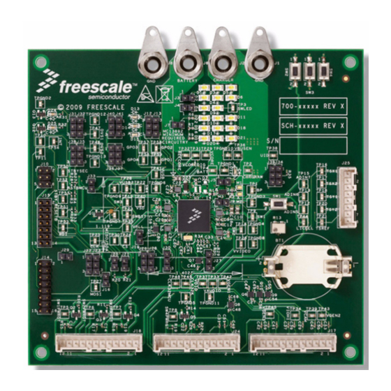
MC13892 Evaluation Board
Supports KIT13892VKEVBEJ and KIT13892VLEVBEJ
Table of Contents
1 Kit Contents / Packing List . . . . . . . . . . . . . . . . . . . . . . . . . . . . . . . . . . . . . . . . . . . . . . . . . . . . . . . . . . . . . . . . . . . . . . . . . . . . . . . . . . . . . . . . .2
2 Important Notice . . . . . . . . . . . . . . . . . . . . . . . . . . . . . . . . . . . . . . . . . . . . . . . . . . . . . . . . . . . . . . . . . . . . . . . . . . . . . . . . . . . . . . . . . . . . . . . . .3
3 Introduction . . . . . . . . . . . . . . . . . . . . . . . . . . . . . . . . . . . . . . . . . . . . . . . . . . . . . . . . . . . . . . . . . . . . . . . . . . . . . . . . . . . . . . . . . . . . . . . . . . . . .4
4 Required Equipment . . . . . . . . . . . . . . . . . . . . . . . . . . . . . . . . . . . . . . . . . . . . . . . . . . . . . . . . . . . . . . . . . . . . . . . . . . . . . . . . . . . . . . . . . . . . . .8
5 Setup Configuration . . . . . . . . . . . . . . . . . . . . . . . . . . . . . . . . . . . . . . . . . . . . . . . . . . . . . . . . . . . . . . . . . . . . . . . . . . . . . . . . . . . . . . . . . . . . . .8
6 Schematics . . . . . . . . . . . . . . . . . . . . . . . . . . . . . . . . . . . . . . . . . . . . . . . . . . . . . . . . . . . . . . . . . . . . . . . . . . . . . . . . . . . . . . . . . . . . . . . . . . . .16
7 Software . . . . . . . . . . . . . . . . . . . . . . . . . . . . . . . . . . . . . . . . . . . . . . . . . . . . . . . . . . . . . . . . . . . . . . . . . . . . . . . . . . . . . . . . . . . . . . . . . . . . . .20
8 KIT13892VKEVBEJ Board Layout . . . . . . . . . . . . . . . . . . . . . . . . . . . . . . . . . . . . . . . . . . . . . . . . . . . . . . . . . . . . . . . . . . . . . . . . . . . . . . . . . .40
9 KIT13892VLEVBEJ Board Layout . . . . . . . . . . . . . . . . . . . . . . . . . . . . . . . . . . . . . . . . . . . . . . . . . . . . . . . . . . . . . . . . . . . . . . . . . . . . . . . . . .45
10 KITUSBCOMDGL Board Layout . . . . . . . . . . . . . . . . . . . . . . . . . . . . . . . . . . . . . . . . . . . . . . . . . . . . . . . . . . . . . . . . . . . . . . . . . . . . . . . . . . .50
11 KIT13892VxEVBEJ Bill of Material . . . . . . . . . . . . . . . . . . . . . . . . . . . . . . . . . . . . . . . . . . . . . . . . . . . . . . . . . . . . . . . . . . . . . . . . . . . . . . . . .54
12 KITUSBCOMDGLEVME Bill of Material . . . . . . . . . . . . . . . . . . . . . . . . . . . . . . . . . . . . . . . . . . . . . . . . . . . . . . . . . . . . . . . . . . . . . . . . . . . . .56
13 References . . . . . . . . . . . . . . . . . . . . . . . . . . . . . . . . . . . . . . . . . . . . . . . . . . . . . . . . . . . . . . . . . . . . . . . . . . . . . . . . . . . . . . . . . . . . . . . . . . .58
14 Revision History . . . . . . . . . . . . . . . . . . . . . . . . . . . . . . . . . . . . . . . . . . . . . . . . . . . . . . . . . . . . . . . . . . . . . . . . . . . . . . . . . . . . . . . . . . . . . . .59
© Freescale Semiconductor, Inc., 2011-2014. All rights reserved.
Figure 1. MC13892 Evaluation Boards
Document Number: KT13892UG
Rev. 4.0, 8/2014
Advertisement
Table of Contents

Related Manuals for NXP Semiconductors Freescale MC13892


Summary of Contents for NXP Semiconductors Freescale MC13892
-
Page 1: Table Of Contents
Freescale Semiconductor Document Number: KT13892UG Rev. 4.0, 8/2014 User’s Guide MC13892 Evaluation Board Supports KIT13892VKEVBEJ and KIT13892VLEVBEJ Figure 1. MC13892 Evaluation Boards Table of Contents 1 Kit Contents / Packing List ..................2 2 Important Notice . -
Page 2: Kit Contents / Packing List
Kit Contents / Packing List Kit Contents / Packing List • KIT13892VxEVBEJ • Kit KITUSBCOMDGLEVME • Cables (8): • 7x2 Flat Ribbon Cable (GPIO) • 8x2 Flat Ribbon Cable (SPI) • 3x2 Flat Ribbon Cable (I • 1x12 Flat Ribbon Cable (3 each) (Application Peripherals) •... -
Page 3: Important Notice
Important Notice Important Notice Freescale provides the enclosed product(s) under the following conditions: This evaluation kit is intended for use of ENGINEERING DEVELOPMENT OR EVALUATION PURPOSES ONLY. It is provided as a sample IC pre-soldered to a printed circuit board to make it easier to access inputs, outputs, and supply terminals. -
Page 4: Introduction
Introduction Introduction KIT13892VXEVBEJ This EVB shows the functionality of the MC13892JVxx device set up under specific operation parameters. The MC13892 is a SMARTMOS Power Management Integrated Circuit (PMIC) component for Freescale's i.MX51, i.MX37, i.MX35, and i.MX27 application processors, targeting netbooks, ebooks, mobile internet devices, smart phones, personal media players, and personal navigation devices. - Page 5 Introduction KITUSBCOMDGLEVME Functional Blocks Table 1. SPI Interface.- Pin Header Configuration for SPI Interface at J9 PIN NUMBER DESCRIPTION PIN NUMBER DESCRIPTION GND - Ground SPSCK - SPI Serial Clock ADC1 - Analog-to-Digital Regulator PWM3 - Pulse Width Modulation Signal COMM_V - Communication Voltage MOSI - SPI Master Output Slave Input ADC0 - Analog-to-Digital Regulator...
- Page 6 Introduction Communication voltage selection - This communication board allows the user to select one of the following three communication voltages through hardware, which are very common on most of the applications: • 5.0 V - This voltage comes directly from the USB port and can be selected by connecting J3(1-2). This selection ignores the voltage coming from the LDO, and sets the USB voltage as the maximum level for communication.
- Page 7 Introduction EVBs Features KIT13892KVxEVBEJ Board • Four Layer Board • Low Noise Design • Top and bottom Layer component placement • Three 12 pin connectors (J17, J18, and J24) for regulators, linear regulators, and NMOS power gate switches accessibility. Review Figures 9 schematics for connections •...
-
Page 8: Required Equipment
Required Equipment Required Equipment • 3.7 V Li-Ion battery to be connected at J6-J8 • 9.0 V, 500 mA power supply to be connected at test point SWLED. • 5.0 V, 5.0 A, Adjustable Power Source to be connected at J1-J2 •... - Page 9 Setup Configuration Figure 2. SPI Configuration for the MC13892JVL Board alongside the USB Dongle Figure 3. I C Configuration for the MC13892JVL Board alongside the USB Dongle MC13892 Evaluation Board Supports KIT13892VKEVBEJ and KIT13892VLEVBEJ, Rev. 4.0 Freescale Semiconductor...
- Page 10 Setup Configuration Figure 4. SPI Configuration for the MC13892JVK Board alongside the USB Dongle Figure 5. I C Configuration for the MC13892JVK Board alongside the USB Dongle MC13892 Evaluation Board Supports KIT13892VKEVBEJ and KIT13892VLEVBEJ, Rev. 4.0 Freescale Semiconductor...
- Page 11 Setup Configuration KIT13892VxEVBEJ Jumper Location and Configuration Figure 6. KIT13892VLEVBEJ Default Jumper Location and Configuration Location Jumper Reference Position J40-41 Shorted Shorted Shorted J22-23 Shorted J36-37 MC13892 Evaluation Board Supports KIT13892VKEVBEJ and KIT13892VLEVBEJ, Rev. 4.0 Freescale Semiconductor...
- Page 12 Setup Configuration Figure 7. KIT13892VKEVBEJ Default Jumper Location and Configuration Location Jumper Reference Position J40-41 J36-37 Shorted Shorted J22-23 Shorted Shorted MC13892 Evaluation Board Supports KIT13892VKEVBEJ and KIT13892VLEVBEJ, Rev. 4.0 Freescale Semiconductor...
- Page 13 Setup Configuration Jumper General Position Function Reference Description Open (default) B type plug (USB Host, OTG default master or no device) is attached J34-J39 USB ID Connection Grounded: A type plug (USB default slave) is attached Resistor to ground: Non-USB accessory is attached Tied to SWBST: Factory mode Control VBUSEN pin Open (default) VBUSEN feature not used J26-J28...
- Page 14 Setup Configuration Jumper General Position Function Reference Description SPIVCC pin allowed to be supplied through connectors J10, J15, or J14 SPIVCC Supply Open Shorted SPIVCC supplied by SW4 (default) Open (default) CS pin allowed to be controlled by connector J15. If it is grounded or left open at startup, the CS pin Control device will be configured on SPI mode.
- Page 15 Setup Configuration KITUSBCOMDGLEVME Jumper Location and Configuration Figure 8. KITUSBCOMDGLEVME Default Jumper Location and Configuration Location Jumper Reference Position Jumper General description Position Function Reference Adjust LDO voltage to 3.3 V 1 - 2 Level shifted Communication voltage Adjust LDO voltage to 1.8 V 2 –...
-
Page 16: Schematics
Schematics Schematics Figure 9. KIT13892VKEVBEJ Schematic (7.0x7.0) MC13892 Evaluation Board Supports KIT13892VKEVBEJ and KIT13892VLEVBEJ, Rev. 4.0 Freescale Semiconductor... - Page 17 Schematics Figure 10. KIT13892VLEVBEJ Schematic (12x12) MC13892 Evaluation Board Supports KIT13892VKEVBEJ and KIT13892VLEVBEJ, Rev. 4.0 Freescale Semiconductor...
- Page 18 Schematics USB Connector Type A USB_PWR MAIN IC USB_PWR VUSB33 MC9S08JM8CLC USB_PWR USB_PWR 270.0 270.0 0.10UF 0.10UF 10UF 10UF USB_PWR 0.47UF 0.47UF 4.7UF 4.7UF 0.5A 0.5A HSMG-C170 HSMG-C170 0.10UF 0.10UF USB_PWR USB_TYPE_A USB_TYPE_A HI1812V101R-10 HI1812V101R-10 PWMSYNC USBDN IRQ/TPMCLK PTC1/SDA RST_JM60 RESET PTC0/SCL PWM3...
- Page 19 Schematics VOLTAGE TRANSLATORS ESD PROTECTION LDO_V USB_PWR GPIOs ( COMM_V ) GTL2010BS GTL2010BS 220K 220K PWM0_VT GPIO2_VT SREF GREF1 GREF DREF1 0.10UF 0.10UF DREF PWM0 GPIO2 LDO_V USB_PWR USB_PWR ( COMM_V ) LDO_V 220K 220K ( COMM_V ) USB_PWR 220K 220K GREF3 SREF...
-
Page 20: Software
Software Software Installing the MC13892 GUI. The Setup installer will be provided as the MC13892 Installer.exe file. Double-Click to the executable file. The installer shall run immediately and will look like as depicted in Figure Figure 13. License Agreement Press the “I Agree” button to continue with the installation process. Figure 14 shows the application components and the device drivers for the USB Dongle. - Page 21 Software Figure 14. Choose Component Window Figure 15. Choose Install Location Before the installer runs, all needed files are stored in the C:/Program Files/MC13892 folder. Once the destination folder is selected, click “Install”. The installation of the necessary drivers begins (Figure 16).
- Page 22 Software Figure 16. Software Install Window Following the correct installation of the GUI and device drivers, the KIT13892VxEVBEJ board is ready to receive and send commands to the MC13892 Installer.exe application thru the KITUSBCOMDGLEVME board. To finish the installation process, select the “Close” button (Figure 17).
- Page 23 Software Controlling the Hardware from the Graphical User interface To interface the KITUSBCOMDGLEVME with KIT13892VxEVBEJ, the following connections should be made: KITUSBCOMDGLEVME KIT13892Vx EVBEJ Function Connector Connector For Control signals: WDI, INT, RESETB, RESETBMCU, STANDBY, STANDBYSEC, CHRGSE1B, CS, and PWRON1. If SPI communication is desired.
- Page 24 Software Figure 19. Communication Type Selection Window for the SPI Figure 20. Communication Type Selection Window for SCI After selecting the communication type, go to the “Board Validation” tab (reference Figure 31 {5}) and set the WDI pin high, toggle the PWRON1 button to ON, and the MC13892 will turn on. If the I C mode is selected (Figure 20), the user...
- Page 25 Software On the example (Figure 22), the “Power” tab has been selected (1); this tab controls the registers for the Linear Regulators, Backlight, and RGB LED blocks. On the Buck Regulators 1 and 2/PLL sub tab (2), all the functions of these two regulators and the PLL frequency can be changed.
- Page 26 Software Power Tab Figure 23. Linear Regulator Configuration Screen The POWER tab includes all the controls to configure the set point of all the LDOs and regulators (1), as well as enable/disable them (2), configure the operation mode (3), and in the case of VGEN3 and VCAM, configure them to work with their internal or external pass device (4).
- Page 27 Software Figure 24. Regulators Configuration Tab Screen In the case of the regulators, the configuration features include for example, other than the normal mode set point, the standby set point (1), the operating mode in normal and standby modes (2), whether they will be enabled or disabled in Memory Hold and User Off modes (3), and in the case of regulators 1 and 2, the Dynamic Voltage Scaling (DVS settings) and the Regulator Increment/Decrement set point (SIDMIN, SIDMAX) (4 and 5 respectively).
- Page 28 Software Figure 25. White LED Backlighting Configuration Tab Screen The Backlight and Tri-color LED sub-tabs include the controls to configure the Ramp and High Current Mode of the LED drivers (1), and combo boxes to set the duty cycle and current setting of the PWM drivers (2). The Continuously On/Off buttons (3) set the duty cycle of the corresponding PWM controller to 32/32 or 0/32 respectively.
- Page 29 Software Charger/Power Control Tab Figure 26. Battery Charger Configuration Tab Screen The charger settings can be configured on the Charger sub-tab: The charger Voltage and Current (1), Power Limiter settings (2), Trickle LED (3), and bits for Software Controlled Charging configuration (4). MC13892 Evaluation Board Supports KIT13892VKEVBEJ and KIT13892VLEVBEJ, Rev.
- Page 30 Software ADC and Coulomb Counter Tabs Figure 27. ADC Configuration Tab Screen The MC13892 Graphical User Interface can control the ADC module in an automatic or manual method. For automatic mode, the ADC tab has two special buttons: • Read ADC Channel (Single Mode) (1) •...
- Page 31 Software Figure 28. Coulomb Counter Configuration Tab Screen On the Coulomb Counter tab, a function called “Initialize CC Counter Automatically” (1) performs the following sequence of commands: • Start the Coulomb Counter • Reset the Coulomb Counter • Set the CCDITHER bit, which applies a dithering to the A to D regulator to avoid any error in the measurement, due to repetitive events •...
- Page 32 Software 7.5.2 Plot Settings (5) The plot setting section manages the general settings of the graphical section in the CC Counter tab. The “Line Style” option tells the graph to display data using different painting styles such as solid, dash, and dot type lines. The “Display Mode”...
- Page 33 Software The digital clock control (1) shows the current time of the RTC register of the MC13892. It is important to enable the RTC (2) and click on the “Send Command” button for it to begin. The time can be changed at any moment using the control text boxes (3).
- Page 34 Software Figure 30. Interrupts Status Tab Screen Board Validation and Scripts Tabs These are two special tabs that control the overall functionality of the device, instead of a specific block like the rest of the tabs. The “Register” combo box (1) contains a list of all the MC13892 registers, in which contents will be shown on the “Bytes” buttons (2) when they are selected in the combo box.
- Page 35 Software Figure 31. Board Validation Configuration Screen 7.9.1 Writing and Running a Script Figure 32. Script Writing Configuration Command Section MC13892 Evaluation Board Supports KIT13892VKEVBEJ and KIT13892VLEVBEJ, Rev. 4.0 Freescale Semiconductor...
- Page 36 Software A complete list of commands can be saved in a file to be run in series as a script. This is done with the “Board Validation” and “Scripts” tabs. To accomplish this, first click on the “Normal Mode” button (1) in Figure 31.
- Page 37 Software 7.10 Running a Script Once the script has been saved, the “Scripts” tab has all the controls to run it. In the “Control Panel” section (1), click on the “Read Script File” button and load the script. A list of all the commands of the loaded script will appear in the “Command”...
- Page 38 Software Click on the “Create Command” button Select the “Assign Name to Group” option, and write “Turn on Sequence” in the group name text box Click on the “Create Group” button In the “Registers” combo box, select the “LED Control 2” register, and with the “Bytes” buttons set the following value: 10010000 00001001 00000000.
- Page 39 Software Ensure the Read/Write button says “Write” and set a command delay of 100 ms. The command iterations and limits can be left with the default values Click on the “Create Command” button In the “Registers” combo box, select the “ADC 1” register, and with the “Bytes” buttons set the following value: 00000000 00000000 00000111.
-
Page 40: Kit13892Vkevbej Board Layout
KIT13892VKEVBEJ Board Layout KIT13892VKEVBEJ Board Layout Assembly Top Figure 34. 13892VK Top Assembly Layer MC13892 Evaluation Board Supports KIT13892VKEVBEJ and KIT13892VLEVBEJ, Rev. 4.0 Freescale Semiconductor... - Page 41 KIT13892VKEVBEJ Board Layout Top Layout Figure 35. 13892VK Top Layout Layer MC13892 Evaluation Board Supports KIT13892VKEVBEJ and KIT13892VLEVBEJ, Rev. 4.0 Freescale Semiconductor...
- Page 42 KIT13892VKEVBEJ Board Layout Bottom Layout Figure 36. 13892VK Bottom Layout Layer MC13892 Evaluation Board Supports KIT13892VKEVBEJ and KIT13892VLEVBEJ, Rev. 4.0 Freescale Semiconductor...
- Page 43 KIT13892VKEVBEJ Board Layout Bottom Assembly and Silk Screen Figure 37. 13892VJ bottom assembly and silk screen layer MC13892 Evaluation Board Supports KIT13892VKEVBEJ and KIT13892VLEVBEJ, Rev. 4.0 Freescale Semiconductor...
- Page 44 KIT13892VKEVBEJ Board Layout Fabrication Drawing Figure 38. 13892VK Fabrication Drawing MC13892 Evaluation Board Supports KIT13892VKEVBEJ and KIT13892VLEVBEJ, Rev. 4.0 Freescale Semiconductor...
-
Page 45: Kit13892Vlevbej Board Layout
KIT13892VLEVBEJ Board Layout KIT13892VLEVBEJ Board Layout Assembly Top Figure 39. 13892VL Top Assembly and Silk Screen Layer MC13892 Evaluation Board Supports KIT13892VKEVBEJ and KIT13892VLEVBEJ, Rev. 4.0 Freescale Semiconductor... - Page 46 KIT13892VLEVBEJ Board Layout Top Layout Figure 40. 13892VL Top Layout Layer MC13892 Evaluation Board Supports KIT13892VKEVBEJ and KIT13892VLEVBEJ, Rev. 4.0 Freescale Semiconductor...
- Page 47 KIT13892VLEVBEJ Board Layout Bottom Layout Figure 41. 13892VL Bottom Layout Layer MC13892 Evaluation Board Supports KIT13892VKEVBEJ and KIT13892VLEVBEJ, Rev. 4.0 Freescale Semiconductor...
- Page 48 KIT13892VLEVBEJ Board Layout Bottom Assembly and Silk Screen Figure 42. 13892 Bottom Assembly and Silk Screen Layer MC13892 Evaluation Board Supports KIT13892VKEVBEJ and KIT13892VLEVBEJ, Rev. 4.0 Freescale Semiconductor...
- Page 49 KIT13892VLEVBEJ Board Layout Fabrication Drawing Figure 43. 13892VL Fabrication Drawing MC13892 Evaluation Board Supports KIT13892VKEVBEJ and KIT13892VLEVBEJ, Rev. 4.0 Freescale Semiconductor...
-
Page 50: Kitusbcomdgl Board Layout
KITUSBCOMDGL Board Layout 10 KITUSBCOMDGL Board Layout 10.1 Assembly Top Figure 44. USBCONDG Top Assembly Layer 10.2 Bottom Layout Figure 45. USBCOMDG Bottom Layout Layer MC13892 Evaluation Board Supports KIT13892VKEVBEJ and KIT13892VLEVBEJ, Rev. 4.0 Freescale Semiconductor... - Page 51 KITUSBCOMDGL Board Layout 10.3 Top Layout Figure 46. USBCOMDG Top Layout Layer MC13892 Evaluation Board Supports KIT13892VKEVBEJ and KIT13892VLEVBEJ, Rev. 4.0 Freescale Semiconductor...
- Page 52 KITUSBCOMDGL Board Layout 10.4 Fabrication Drawing Figure 47. USBCOMDG Fabrication Drawing MC13892 Evaluation Board Supports KIT13892VKEVBEJ and KIT13892VLEVBEJ, Rev. 4.0 Freescale Semiconductor...
- Page 53 KITUSBCOMDGL Board Layout 10.5 Silk Screen Bottom Figure 48. USBCOMDG Bottom Silk Screen Layer. 10.6 Silk Screen Top Figure 49. USBCOMDG Top Silk Screen Layer MC13892 Evaluation Board Supports KIT13892VKEVBEJ and KIT13892VLEVBEJ, Rev. 4.0 Freescale Semiconductor...
-
Page 54: Kit13892Vxevbej Bill Of Material
KIT13892VxEVBEJ Bill of Material 11 KIT13892VxEVBEJ Bill of Material Reference Value Description Manufacturer Part Number HU2477N-LF Battery Holder CR2477 Top Load Horizontal TH Renata Batteries HU2477N-LF C1, C9, C12, C15, C20, 4.7F CAP CER 4.7F 10V 10% X5R 0603 Taiyo Yuden LMK107BJ475KA-T C2, C4, C5 , C6... - Page 55 KIT13892VxEVBEJ Bill of Material Reference Value Description Manufacturer Part Number TRAN MOSFET PWR SGL P-CHANNEL 8V NTHS2101P ON Semiconductor NTHS2101PT1G 7.5A CHIPFET Q1,Q12,Q13 2N7002 TRAN NMOS 60V 115MA SOT23 ON Semiconductor 2N7002LT1G MGSF1N02L Q2,Q3,Q4,Q5 TRAN NMOS PWR 20V 750MA ON Semiconductor MGSF1N02LT1G NSS12100U Q6,Q7,Q8,Q9,Q10,Q11...
-
Page 56: Kitusbcomdglevme Bill Of Material
KITUSBCOMDGLEVME Bill of Material 12 KITUSBCOMDGLEVME Bill of Material Reference Value Description Manufacturer Part Number Freescale MC9S08JM8CLCE IC MCU 8BIT 8K FLASH 1K RAM 48MHZ 2.7-5.5 LQFP32 MC9S08JM8CLCE Semiconductor CAP CER 0.47F 16V 10% X7R 0603 Kemet C0603C474K4RAC 0.47F C2, C5, 0.10F C8, C9, C14, C16,... - Page 57 RES MF 20K 1/10W 5% 0603 Bourns CR0603-JW-203ELF Test Point Pin.138X.059 SMT Nicomatic C12000B TEST POINT IC VXLTR BIDIR 10BIT GTL-TVC 1.0-5.0V HVQFN24 NXP Semiconductors GTL2010BS GTL2010BS IC,L,MAX232A,RS232 SO16 Maxim MAX232ACSE MAX232A U4, U5, U6 IC VXLTR BIDIR 2BIT GTL-TVC 1.0-5.0V VSSOP8...
-
Page 58: References
References 13 References The following list contains URLs where you can obtain information on other Freescale products and application solutions: Description Reference Web Sites Reference URL Locations Freescale Web Site http://www.freescale.com/ Freescale’s Analog Web Site www.freescale.com/analog Data Sheet MC13892 http://www.freescale.com/files/analog/doc/data_sheet/MC13892.pdf Freescale Power Management Web Site http://www.freescale.com/webapp/sps/site/taxonomy.jsp?nodeId=01435979961182 MC13892 Evaluation Board Supports KIT13892VKEVBEJ and... -
Page 59: Revision History
Revision History Revision History Revision Date Description of Changes • Updated kit contents/packing list 8/2014 • Added revision history page • Updated back page MC13892 Evaluation Board Supports KIT13892VKEVBEJ and KIT13892VLEVBEJ, Rev. 4.0 Freescale Semiconductor... - Page 60 How to Reach Us: Information in this document is provided solely to enable system and software implementers to use Freescale products. There are no express or implied copyright licenses granted hereunder to design or fabricate any integrated circuits based Home Page: freescale.com on the information in this document.
Need help?
Do you have a question about the Freescale MC13892 and is the answer not in the manual?
Questions and answers