Table of Contents
Advertisement
Quick Links
MCIMX8ULP-EVK9-UM
MCIMX8ULP-EVK9 Board User Manual
Rev. 1 — 25 August 2023
Document information
Information
Keywords
Abstract
Content
MCIMX8ULP-EVK9-UM, MCIMX8ULP-EVK9, i.MX 8ULP, MCIMX8ULP-EVK9BB, MX8ULP-
EVK9SOM, base board, SOM board
MCIMX8ULP-EVK9 is a design and evaluation platform based on NXP i.MX 8ULP application
processor (9.4 mm x 9.4 mm package).
User manual
Advertisement
Table of Contents

Subscribe to Our Youtube Channel
Related Manuals for NXP Semiconductors MCIMX8ULP-EVK9


Summary of Contents for NXP Semiconductors MCIMX8ULP-EVK9
- Page 1 Rev. 1 — 25 August 2023 User manual Document information Information Content Keywords MCIMX8ULP-EVK9-UM, MCIMX8ULP-EVK9, i.MX 8ULP, MCIMX8ULP-EVK9BB, MX8ULP- EVK9SOM, base board, SOM board Abstract MCIMX8ULP-EVK9 is a design and evaluation platform based on NXP i.MX 8ULP application processor (9.4 mm x 9.4 mm package).
-
Page 2: Overview
In addition, MCIMX8ULP-EVK9 facilitates software development with the ultimate goal of faster time to market, by supporting operating systems, including Linux, Android, and FreeRTOS. For information on how to set up and boot MCIMX8ULP-EVK9, see i.MX 8ULP Evaluation Kit 9 Quick Start Guide provided in the MCIMX8ULP-EVK9 hardware kit. -
Page 3: Related Documentation
MCIMX8ULP-EVK9-UM NXP Semiconductors MCIMX8ULP-EVK9 Board User Manual Table 1. Acronyms ...continued Acronym Description Inter-IC Sound Internet of Things Low-dropout regulator Light-emitting diode LPDDR4 Low-Power Double Data Rate Controller LPI2C Low-Power Inter-Integrated Circuit LPUART Low-Power Universal Asynchronous Receiver/Transmitter Medium access control MIPI... -
Page 4: Kit Contents
It also covers special i.MX features and how to use them. 1.3 Kit contents Table 3 lists the items included in the MCIMX8ULP-EVK9 hardware kit. Table 3. Kit contents Item Quantity MCIMX8ULP-EVK9 hardware assembled with two separate boards, MX8ULP- EVK9SOM and MCIMX8ULP-EVK9BB 5 V DC, 5 A power adapter with 2.1 mm x 5.5 mm plug... -
Page 5: Block Diagram
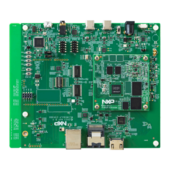
Figure 1. MCIMX8ULP-EVK9 block diagram 1.5 Board pictures Figure 2 shows the top-side view of MCIMX8ULP-EVK9, with SOM board (MX8ULP-EVK9SOM) and base board (MCIMX8ULP-EVK9BB) highlighted. Figure 2. Board top-side view MCIMX8ULP-EVK9-UM All information provided in this document is subject to legal disclaimers. - Page 6 MCIMX8ULP-EVK9-UM NXP Semiconductors MCIMX8ULP-EVK9 Board User Manual SOM board (MX8ULP-EVK9SOM) Base board (MCIMX8ULP-EVK9BB) Figure 3 shows the bottom-side view of MCIMX8ULP-EVK9. Figure 3. Board bottom-side view Figure 4 highlights important SOM board components. Figure 4. SOM board components MCIMX8ULP-EVK9-UM All information provided in this document is subject to legal disclaimers.
-
Page 7: Board Features
PMIC i.MX 8ULP LPDDR4 eMMC Octal SPI NOR (in APD) 1.6 Board features Table 4 lists the features of MCIMX8ULP-EVK9. Table 4. MCIMX8ULP-EVK9 features Board feature Target processor feature Description used Processor NXP i.MX 8ULP processor (part number: MIMX8UD7DVK10SA, package size: 9.4 mm x 9.4 mm) based on up to two Arm Cortex-A35 cores, each running at 800 MHz frequency, and one Arm Cortex-M33F core running at 216 MHz nominal (RUN) frequency. -
Page 8: Connectors
MCIMX8ULP-EVK9-UM NXP Semiconductors MCIMX8ULP-EVK9 Board User Manual Table 4. MCIMX8ULP-EVK9 features ...continued Board feature Target processor feature Description used CAN interface FlexCAN controller HS CAN transceiver with option to connect (populate) a 3-pin CAN header Display interface MIPI-DSI host controller One of the following two options can be used: •... - Page 9 MCIMX8ULP-EVK9-UM NXP Semiconductors MCIMX8ULP-EVK9 Board User Manual CON1 (DNP) (DNP) Figure 5. Connectors (top-side view) Note: In Figure 5, board-to-board connectors between base board and SOM board are hidden. J20 J21 (DNP) J22 J23 (DNP) Figure 6. Connectors (bottom-side view) MCIMX8ULP-EVK9-UM All information provided in this document is subject to legal disclaimers.
- Page 10 MCIMX8ULP-EVK9-UM NXP Semiconductors MCIMX8ULP-EVK9 Board User Manual Table 5 describes the connectors available on the MCIMX8ULP-EVK9BB board. Table 5. Base board connectors Part identifier PCB label Connector type Description Reference section – Coin cell battery holder Holder for ML414 size coin cell Section 2.2...
-
Page 11: Jumpers
MX8ULP-EVK9 SOM board schematics – 2x40-position receptacle 1.8 Jumpers Figure 7 shows the MCIMX8ULP-EVK9 jumpers. All the jumpers are placed on the MCIMX8ULP-EVK9BB board. Figure 7. Jumpers Table 7 describes the MCIMX8ULP-EVK9 jumpers. Table 7. MCIMX8ULP-EVK9 jumpers Part identifier PCB label... -
Page 12: Push And Slide Buttons
MCIMX8ULP-EVK9-UM NXP Semiconductors MCIMX8ULP-EVK9 Board User Manual 1.9 Push and slide buttons Figure 8 shows the MCIMX8ULP-EVK9 push and slide buttons. All these buttons are placed on the MCIMX8ULP-EVK9BB board. SW10 Figure 8. Push and slide buttons Table 8 describes the MCIMX8ULP-EVK9 push and slide buttons. -
Page 13: Dip Switch
SWITCH button 1.10 DIP switch MCIMX8ULP-EVK9 has an 8-pin dual inline package (DIP) switch (SW5) for controlling the i.MX 8ULP boot mode. SW5 is placed on the MCIMX8ULP-EVK9BB board. Each pin of the DIP switch has two positions: • OFF position (pin has value 0) •... -
Page 14: Leds
MCIMX8ULP-EVK9 provides numerous light-emitting diodes (LEDs) for monitoring system status. The information collected from the LEDs can be used for debugging purposes. Figure 10 shows the MCIMX8ULP-EVK9 LEDs. All these LEDs are placed on the MCIMX8ULP-EVK9BB board. MCIMX8ULP-EVK9-UM All information provided in this document is subject to legal disclaimers. - Page 15 MCIMX8ULP-EVK9-UM NXP Semiconductors MCIMX8ULP-EVK9 Board User Manual D35 D36 D29 D28 D9 D10 Figure 10. LEDs Table 10 describes the MCIMX8ULP-EVK9 LEDs. Table 10. MCIMX8ULP-EVK9 LEDs Part identifier LED color Name/function Description (when LED is ON) Green M.2 card WLAN M.2 card wireless LAN is operating correctly.
- Page 16 MCIMX8ULP-EVK9-UM NXP Semiconductors MCIMX8ULP-EVK9 Board User Manual Table 10. MCIMX8ULP-EVK9 LEDs ...continued Part identifier LED color Name/function Description (when LED is ON) Green Lithium-ion battery Battery charger is charging the lithium-ion battery. charger status Note: A blinking LED indicates bad lithium-ion battery.
-
Page 17: Functional Description
WLAN, Bluetooth, GPS, and displays. Also, these two coprocessors are connected to the Cortex-M33F core: PowerQuad and Casper. MCIMX8ULP-EVK9 includes an i.MX 8ULP processor (MIMX8UD7DVK10SA) with this package information: 512 FCCSP, 9.4 mm x 9.4 mm, 0.4 mm pitch. -
Page 18: Board Power Supply
2.2 Board power supply MCIMX8ULP-EVK9 is powered up with an external 5 V DC power supply, through DC power jack P1 available on the base board. The 5 V power supply to the board can be turned on/off using a slide button SW10 connected to a P-channel MOSFET Q21. - Page 19 MCIMX8ULP-EVK9-UM NXP Semiconductors MCIMX8ULP-EVK9 Board User Manual Table 11. MCIMX8ULP-EVK9 power supplies ...continued Power source Manufacturer and part Power Description number supply • PMIC PCA9460A on the SOM board (through board-to- Note: PSU_5V0_4 Note: PSU_ V2 can be produced 5V0_4V2 is...
- Page 20 MCIMX8ULP-EVK9-UM NXP Semiconductors MCIMX8ULP-EVK9 Board User Manual Table 11. MCIMX8ULP-EVK9 power supplies ...continued Power source Manufacturer and part Power Description number supply – I/O expander U27 – Boot mode remote control buffer/driver U30 – I/O isolation buffer U35 – Load switch U58 •...
- Page 21 MCIMX8ULP-EVK9-UM NXP Semiconductors MCIMX8ULP-EVK9 Board User Manual Table 11. MCIMX8ULP-EVK9 power supplies ...continued Power source Manufacturer and part Power Description number supply External supply – VBUS_USB_ Supplies power to LDO regulator U45 through USB micro-B connector J17 LDO regulator U45 Richtek Technology VCC_FT_3V3 •...
-
Page 22: Pmic Supplies
Industrial Products Data Sheet. 2.2.1 PMIC supplies MCIMX8ULP-EVK9 has a power management integrated circuit (PMIC) U6 (NXP PCA9460A), which is placed on the MX8ULP-EVK9SOM board. PMIC allows to configure the power supply rails according to the needs of the current application. - Page 23 MCIMX8ULP-EVK9-UM NXP Semiconductors MCIMX8ULP-EVK9 Board User Manual VDD_PMC18/VDD_FUSE18 VSYS BUCK1 1.8 V VDD_PTB/VDD18_IOREF 1000 mA PMIC_RST_B VDD_PLL18 uPower LDO uPower PCA9460A VDD_ANA18 VREF_ANA18 M33 LDO 1.0 V BUCK2 VDD_DIG0 1000 mA 1.0 V BUCK3 INTB VDD_DIG1 1000 mA VDD_DIG2/VDD_DDR_PLL PMIC_ON_REQ...
- Page 24 MCIMX8ULP-EVK9-UM NXP Semiconductors MCIMX8ULP-EVK9 Board User Manual Table 12. PMIC power supplies Power source Manufacturer and Power supply Description part number PMIC U6 NXP PCA9460A LX1: BUCK1_1V8 (1.8 V) • Produces the following supplies: – BUCK1_DRAM_1V8 – BUCK1_NOR_pSRAM_1V8 – BUCK1_LDOBIAS_1V8 – BUCK1_EMMC_NOR_1V8 •...
- Page 25 MCIMX8ULP-EVK9-UM NXP Semiconductors MCIMX8ULP-EVK9 Board User Manual Table 12. PMIC power supplies ...continued Power source Manufacturer and Power supply Description part number From BUCK1_1V8 – BUCK1_DRAM_1V8 (1.8 V) One of the three power supplies for LPDDR4/ supply LPDDR4x DRAM memory U11...
- Page 26 MCIMX8ULP-EVK9-UM NXP Semiconductors MCIMX8ULP-EVK9 Board User Manual Table 12. PMIC power supplies ...continued Power source Manufacturer and Power supply Description part number From BUCK4_1V1 – BUCK4_DRAM_1V1 (1.1 V) Second power supply for LPDDR4/LPDDR4x supply DRAM memory U11 From BUCK1_ – BUCK1_LSW1_CPU_1V8 Provides VDD_PTC power to the i.MX 8ULP...
-
Page 27: Power Monitoring
• BUCK1_LSW1_1V8 (as VDD_PTC) • LDO4_1V8 (as VDD_PTD) • BUCK1_LSW4_1V8 (as VDD_PTF) 2.2.2 Power monitoring MCIMX8ULP-EVK9 includes five quad-channel power monitors for power and energy monitoring. All the power monitors are placed on the MX8ULP-EVK9SOM board. Table 14 describes the MCIMX8ULP-EVK9 power monitors. -
Page 28: Power Rails Under Measurement
MCIMX8ULP-EVK9-UM NXP Semiconductors MCIMX8ULP-EVK9 Board User Manual Table 14. Power monitors ...continued Part identifier Manufacturer and part 7-bit I2C address Power rails number • LDO1_CPU_1V1 • BUCK1_LSW1_CPU_1V8 • BUCK1_LSW4_CPU_1V8 A 7-bit address does not include the read/write (R/W) bit. 2.2.2.1 Power rails under measurement Table 15 provides details about MX8ULP-EVK9SOM board power rails tested by NXP. -
Page 29: Clocks
• Higher sampling resolution of BCU • Enhanced visibility of power rail activities of PMT This document only shows the power measurement functions for MCIMX8ULP-EVK9. For more information about BCU and PMT, see Board Control Utilities Release Notes in GitHub and i.MX Power Measurement Tool... -
Page 30: Emmc Memory
Description U5 (on SOM board) Western Digital SDINBDA6-32G-I 32 GB eMMC NAND flash memory The eMMC memory is the default boot device for the i.MX 8ULP processor on MCIMX8ULP-EVK9. For information on boot mode settings, see Table 2.6 FlexSPI interface The i.MX 8ULP processor has three Flexible Serial Peripheral Interface (FlexSPI) controllers: FlexSPI0,... -
Page 31: Ethernet Interface
The i.MX 8ULP processor has two independent USB 2.0 On-The-Go (OTG) controllers: USB0 and USB1. Both the controllers provide host and device functionality with support for OTG. On MCIMX8ULP-EVK9, each USB OTG controller connects to a USB Type-C connector, as explained in Table Table 20. USB connectors... -
Page 32: Can Interface
The i.MX 8ULP processor has a Flexible Controller Area Network (FlexCAN) controller, which supports CAN with flexible data-rate (FD). MCIMX8ULP-EVK9 supports communication with the FlexCAN controller through a high-speed (HS) CAN transceiver U24 (NXP TJA1057GT/3), which provides differential transmit and receive capabilities to the FlexCAN controller. -
Page 33: Display Interface
The Inter-Integrated Circuit (I2C) protocol is a serial bus protocol that allows multiple peripheral devices to communicate to one or more master devices with a pair of control and data signals. In MCIMX8ULP-EVK9, I2C interface is implemented through I2C buses from two I2C masters, described in Table 23. - Page 34 Processor domain I2C master Description FT4232H USB-to-UART/MPSSE bridge (U37). Table 24 shows the MCIMX8ULP-EVK9 I2C bus device map. Note: Unless specified explicitly, the part identifiers mentioned in Table 24 correspond to the MCIMX8ULP- EVK9BB board. Table 24. I2C bus device map...
- Page 35 MCIMX8ULP-EVK9-UM NXP Semiconductors MCIMX8ULP-EVK9 Board User Manual Table 24. I2C bus device map ...continued I2C bus 7-bit I2C Device Description address 0x10 Microchip Technology Power monitors PAC1934T-I/J6CX (U15 on SOM board) 0x11 Microchip Technology PAC1934T-I/J6CX (U18 on SOM board) 0x12 Microchip Technology...
-
Page 36: Audio Codec
The onboard audio codec is connected to a 3.5 mm audio stereo headphone jack J14 (Fodot Electronics KJ366EYS) for audio input/output. • External audio codec option: MCIMX8ULP-EVK9 has a 2x5-pin header J12 for connecting an external codec. Communication between the onboard/external audio codec and the processor is enabled using I2C bus (for control signals) and I2S bus (for data signals). -
Page 37: Temperature Sensor
For more information, see nxp.com. 2.14.1 Temperature sensor MCIMX8ULP-EVK9 has a digital temperature sensor (NXP PCT2075), which is placed on the MX8ULP- EVK9SOM board (part identifier: XU28). By default, the interrupt signal of the temperature sensor is open drain. The temperature sensor is controlled through the I2C bus (FTB) of the USB-to-UART/MPSSE bridge (U37 on base board) and its 7-bit I2C address is 0x48. -
Page 38: Connector And Wi-Fi/Bluetooth Module
Not connected 2.16 M.2 connector and Wi-Fi/Bluetooth module MCIMX8ULP-EVK9 has a 75-pin, M.2 Key-E mini card connector J19 for plugging a Wi-Fi/Bluetooth card. The M.2 mini card connector supports communication with the LPUART6, LPI2C7, uSDHC2, SAI6, and USB1 controller of the i.MX 8ULP processor. -
Page 39: Arduino Connectors
68, 70, 71, 73 Note: For more details about i.MX 8ULP interfaces, see i.MX 8ULP Processor Reference Manual. The MCIMX8ULP-EVK9 kit comes with a Wi-Fi + Bluetooth card to be used on the M.2 connector. Table 31 describes the Wi-Fi + Bluetooth card. - Page 40 MCIMX8ULP-EVK9-UM NXP Semiconductors MCIMX8ULP-EVK9 Board User Manual Table 32. J20 pinout ...continued Pin number Function Processor pin Processor domain LPSPI5_PCS0 / LPUART6_RX/TPM5_CH0 / I2S5_ PTF19 RX_BCLK LPSPI5_SOUT / LPUART6_RTS_b/ I2C6_SDA / PTF17 TPM4_CH5 / I2S4_TXD0 LPSPI5_SIN / LPUART6_CTS_b/ LPI2C6_SCL / PTF16...
-
Page 41: I/O Multiplexers
• Multiplexer for JTAG signal muxing (Section 2.18.3) 2.18.1 DSI/SPDIF signal muxing MCIMX8ULP-EVK9 provides a set of three multiplexers for muxing processor DSI and SPDIF signals between MIPI-to-HDMI transmitter U10 and MIPI-DSI + touch connector J18. Table 36 describes the DSI and SPDIF signal multiplexers. -
Page 42: Jtag Signal Muxing
• 1: LPUART/I2S signals are routed to the Arduino connector J20. 2.18.3 JTAG signal muxing MCIMX8ULP-EVK9 provides the following two remote JTAG debugging options for i.MX 8ULP processor: • Using a JTAG debugger connected through JTAG header J13 • Using USB debug host through channel A of USB-to-UART/MPSSE bridge U37... -
Page 43: System Id Eeprom
AN13119, i.MX Power Measurement Tool. 2.20.1 System ID EEPROM MCIMX8ULP-EVK9 provides a memory placeholder U1 for adding a 2 kbit system ID EEPROM (Microchip Technology AT24C02C-XHM-B). U1 is controlled through the I2C bus of channel B of USB-to-UART/MPSSE bridge U37. -
Page 44: Boot Configuration
Table 9 describes how to select boot configuration using SW5. Note: For information on how to set up and boot MCIMX8ULP-EVK9, see i.MX 8ULP Evaluation Kit 9 Quick Start Guide provided with the MCIMX8ULP-EVK9 hardware kit. MCIMX8ULP-EVK9-UM All information provided in this document is subject to legal disclaimers. -
Page 45: Usb Debug Connector
MCIMX8ULP-EVK9-UM NXP Semiconductors MCIMX8ULP-EVK9 Board User Manual 2.20.3 USB debug connector MCIMX8ULP-EVK9 has a USB 2.0 micro-B connector that allows to connect the i.MX 8ULP processor to the host computer for debugging purposes. Table 42 describes the USB debug connector. -
Page 46: Board Errata
MCIMX8ULP-EVK9-UM NXP Semiconductors MCIMX8ULP-EVK9 Board User Manual Figure 14. MX8ULP-EVK9SOM PCB stack-up information Figure 15 shows the MCIMX8ULP-EVK9BB PCB stack-up information. Figure 15. MCIMX8ULP-EVK9BB PCB stack-up information 2.22 Board errata None MCIMX8ULP-EVK9-UM All information provided in this document is subject to legal disclaimers. -
Page 47: Revision History
MCIMX8ULP-EVK9-UM NXP Semiconductors MCIMX8ULP-EVK9 Board User Manual 3 Revision history Table 44 summarizes the revisions to this document. Table 44. Revision history Revision number Release date Description 25 August Initial public release MCIMX8ULP-EVK9-UM All information provided in this document is subject to legal disclaimers. -
Page 48: Legal Information
NXP Semiconductors. In the event that customer uses the product for design-in and use in In no event shall NXP Semiconductors be liable for any indirect, incidental, automotive applications to automotive specifications and standards, punitive, special or consequential damages (including - without limitation - customer (a) shall use the product without NXP Semiconductors’... - Page 49 MCIMX8ULP-EVK9-UM NXP Semiconductors MCIMX8ULP-EVK9 Board User Manual AMBA, Arm, Arm7, Arm7TDMI, Arm9, Arm11, Artisan, big.LITTLE, Cordio, CoreLink, CoreSight, Cortex, DesignStart, DynamIQ, Jazelle, Keil, Mali, Mbed, Mbed Enabled, NEON, POP, RealView, SecurCore, Socrates, Thumb, TrustZone, ULINK, ULINK2, ULINK-ME, ULINK- PLUS, ULINKpro, μVision, Versatile — are trademarks and/or registered trademarks of Arm Limited (or its subsidiaries or affiliates) in the US and/or elsewhere.
-
Page 50: Table Of Contents
MCIMX8ULP-EVK9-UM NXP Semiconductors MCIMX8ULP-EVK9 Board User Manual Contents Overview .............. 2 Acronyms ............2 Related documentation ........3 Kit contents ............4 Block diagram ............5 Board pictures ........... 5 Board features ........... 7 Connectors ............8 Jumpers ............11 Push and slide buttons ........12 1.10...
Need help?
Do you have a question about the MCIMX8ULP-EVK9 and is the answer not in the manual?
Questions and answers