Advertisement
Quick Links
Advertisement

Subscribe to Our Youtube Channel
Related Manuals for Insportline CC200


Summary of Contents for Insportline CC200
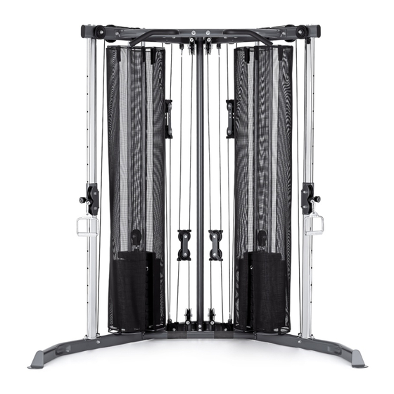
- Page 1 USER MANUAL – EN IN 17963 Power Rack inSPORTline Cable Column CC200...
- Page 2 CONTENTS EXPLODED-VIEW ........................... 3 PARTS LIST ............................4 ASSEMBLY INSTRUCTIONS ......................... 6 TERMS AND CONDITIONS OF WARRANTY, WARRANTY CLAIMS ..........12...
-
Page 3: Exploded-View
EXPLODED-VIEW 29 30... -
Page 4: Parts List
PARTS LIST NUMBER DESCRIPTION QUANTITY JOINT BASE JOINT TUBE RIGHT BASE UPRIGHT FRAME ADJUSTMENT TUBE AXES STRAIGHT BEAM GUIDE ROD TOP JOINT TUBE TOP CROSS BEAM JOINT BEAM JOINT ROD ADJUSTABLE PULLEY BLOCK PULLEY BLOCK SWIVEL PULLEY BLOCK (I) SWIVEL PULLEY BLOCK (II) SWIVEL PULLEY BLOCK (III) SWIVEL PULLEY BLOCK (IV) TOP PLATE... - Page 5 CABLE (I) CABLE (II) CABLE (III) HEX HEAD BOLT M8*16 HEX HEAD BOLT M10*16 HEX HEAD BOLT M8*28 HEX HEAD BOLT M10*48 NUT M12 HEX HEAD BOLT M10*55 HEX HEAD BOLT M10*60 HEX HEAD BOLT M10*68 HEX HEAD BOLT M10*75 HEX HEAD BOLT M10*80 HEX HEAD BOLT M10*85 HEX HEAD BOLT M10*70...
-
Page 6: Assembly Instructions
ASSEMBLY INSTRUCTIONS STEP 1 15 29 15 29 21 29 12 26 29 30 1. Attach right base (C) and left base (AA) to joint base (A) with (17), (29) and (30). 2. Attach joint tube (B) to right base (C) and left base (AA) with (17), (18), (29) and (30). 3. - Page 7 STEP 2 18 21 20 30 19 28 7. Slide rubber donut (3) onto guide rod (H).
- Page 8 8. Slide weight plate (T) onto guide rod (H), insert selector rod (U) into weight plate (T) with pin (8). 9. Slide top plate (S) onto guide rod (H), attach secure bushing (V) to selector rod (U), and attach swivel pulley block IV (R) with (16) and big washer (32) to selector rod (U) as shown. 10.
- Page 9 CABLE 1...
- Page 10 CABLE 2...
- Page 11 CABLE 3...
-
Page 12: Terms And Conditions Of Warranty, Warranty Claims
TERMS AND CONDITIONS OF WARRANTY, WARRANTY CLAIMS General Conditions of Warranty and Definition of Terms All Warranty Conditions stated here under determine Warranty Coverage and Warranty Claim Procedure. Conditions of Warranty and Warranty Claims are governed by Act No. 89/2012 Coll. Civil Code, and Act No. - Page 13 26847264 VAT ID: CZ26847264 Phone: +420 556 300 970 E-mail: eshop@insportline.cz reklamace@insportline.cz servis@insportline.cz Web: www.inSPORTline.cz inSPORTline s.r.o. Headquaters, warranty & service center: Električná 6471, Trenčín 911 01, SK CRN: 36311723 VAT ID: SK2020177082 Phone: +421(0)326 526 701 E-mail: objednavky@insportline.sk reklamacie@insportline.sk servis@insportline.sk...
Need help?
Do you have a question about the CC200 and is the answer not in the manual?
Questions and answers