Table of Contents
Advertisement
Quick Links
Installation and Operation Manual
Manual P/N 5900265 — Manual Revision A6 — December 2022
Models:
• 10AP
• 10AP-168
• 10APX
• 10APX-181
Designed and engineered by BendPak Inc. in Southern California, USA. Made in China.
⚠
DANGER
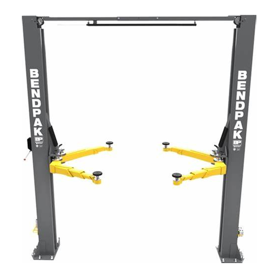
Clearfloor Two-Post Lifts
10AP model shown.
IMPORTANT SAFETY INSTRUCTIONS, SAVE THESE
INSTRUCTIONS
operating, servicing, or maintaining this Lift. Failure to follow the instructions
and safety precautions in this manual can result in serious injury or death.
Make sure all other operators also read this manual. Keep the manual near
the product for future reference. By proceeding with installation and
operation, you agree that you fully understand the contents of this
manual and assume full responsibility for product use .
!
Read this manual thoroughly before installing,
1645 Lemonwood Dr.
Santa Paula, CA 93060 USA
Toll Free: (800) 253-2363
Telephone: (805) 933-9970
bendpak.com
Advertisement
Table of Contents

Related Manuals for BendPak Clearfloor 10AP


Summary of Contents for BendPak Clearfloor 10AP
- Page 1 Models: • 10AP • 10AP-168 • 10APX • 10APX-181 10AP model shown. Designed and engineered by BendPak Inc. in Southern California, USA. Made in China. ⚠ IMPORTANT SAFETY INSTRUCTIONS, SAVE THESE INSTRUCTIONS DANGER Read this manual thoroughly before installing, operating, servicing, or maintaining this Lift. Failure to follow the instructions and safety precautions in this manual can result in serious injury or death.
- Page 2 Copyright. Copyright © 2022 by BendPak Inc. All rights reserved. You may make copies of this document if you agree that: full attribution goes to BendPak Inc., you are not authorized to make changes to the content, you do not gain any rights to this content, and you will not use the copies for commercial purposes.
- Page 3 Unit Information. Enter the Model Number, Serial Number, and the Date of Manufacture from the ID label on your unit. This information is required for part or warranty issues. Model: Serial: Date of Manufacture: 10AP Series Two-Post Lifts P/N 5900265 — Rev. A6 — December 2022...
-
Page 4: Table Of Contents
Technical support and service is available from your dealer, on the Web at bendpak.com/support, by email at support@bendpak.com, or by phone at (800) 253-2363, extension 196. You may also contact BendPak for parts replacement information (please have the model and serial number of your unit available) at (800) 253-2363, extension 191. -
Page 5: Shipping Information
900 chemicals identified by the State of California to cause cancer, birth defects or reproductive harm. Always use this product in accordance with BendPak’s instructions. For more information, visit www.p65warnings.ca.gov. - Page 6 Always wear safety glasses! Everyday glasses only have impact resistant lenses, they are not safety glasses. Save these instructions! Additional Safety Information The following safety information applies to all BendPak 10AP models: • 10AP Series Lifts are Two Post Service Lifts. Use them only for their intended purpose.
- Page 7 BendPak assumes no liability for damages resulting from: • Use of the equipment for purposes other than those described in this manual. • Modifications to the equipment without prior, written permission from BendPak. • Injury or death caused by modifying, disabling, overriding, or removing safety features. •...
-
Page 8: Components
Components Not all components shown. Models with extensions are taller. Reference only – do not scale. 10AP Series Two-Post Lifts P/N 5900265 — Rev. A6 — December 2022... -
Page 9: Specifications
Specifications Top View Approach View Reference only – do not scale. 10AP Series Two-Post Lifts P/N 5900265 — Rev. A6 — December 2022... - Page 10 Model 10AP 10AP-168 10APX 10APX-181 Lifting Capacity 10,000 lbs. / 4,536 kg Max. Capacity — Front Axle 5,000 lbs. / 2,268 kg Max. Capacity — Rear Axle 5,000 lbs. / 2,268 kg A – Max. Rise 69 in. / 1,753 mm 75.5 in.
-
Page 11: Installation Checklist
Installation Checklist Following are the steps needed to install a 10AP Series Two-Post Lift; perform them in this order. ☐ 1. Review the Safety Rules. ☐ 2. Make sure you have the necessary tools. ☐ 3. Plan for Electrical Work. ☐... -
Page 12: Installation
Technical Support at (800) 253-2363. Reviewing the Safety Rules When installing a Lift, your safety depends on proper training and thoughtful operation. BendPak recommends referring to the ANSI/ALI ALIS Standard Safety Requirements for Installation and Service for more information about safely installing, using, and servicing your Lift. - Page 13 Preparing for Electrical Work You will need to have a licensed, certified Electrician available at some point during the installation. ⚠ must DANGER All wiring be performed by a licensed, certified Electrician in accordance with applicable local, state, and federal electrical codes, rules, and regulations, such as state and federal OSHA regulations and electrical codes.
- Page 14 Reviewing the Installation Orientation Keep these factors in mind when deciding how to orient the Lift: • The first thing to figure out is which direction you will be driving the Vehicles in, called the Approach. o In most cases, this is simple: there’s a driveway on one side and a wall on the other side. The driveway is your Approach.
- Page 15 Checking Clearances Clearance around and above the Lift is required for safety . Refer to the figures below. Figures are not to scale. Not all components shown. Additional distance may be required on the Front and Rear to allow Vehicles to be driven in or out from these directions. 10AP Series Two-Post Lifts P/N 5900265 —...
- Page 16 ⚠ CAUTION BendPak Lifts are supplied with installation instructions and concrete anchors that meet the criteria set by the latest version of the American National Standard in Automotive Lifts – Safety Requirements for Construction, Testing, and Validation in., ANSI/ALI ALCTV.
- Page 17 Choosing a Wide or Narrow Configuration 10AP Series Two-Post Lifts can be installed in a Wide or Narrow Configuration: • Wide Configuration. The Posts are farther apart, which means you can raise wider Vehicles on the Lift. This is usually the best choice your Lift location is wide enough to support it.
- Page 18 Installing the Safety Assemblies and Positioning the Safety Lock Cable Leaving both Lift Posts flat on the ground with access to the inside of the Post will ease the Safety Lock installation and threading of the Safety Lock Cable into position. This procedure is intended to leave the cable coiled at the top of the Offside Post, ready for routing after the Posts are standing.
- Page 19 To assemble and install the two Safety Assemblies and pre-position the safety release cable: insides Put both Posts either flat on the ground or elevated on a sawhorse or similar. The of the Posts must be accessible, facing up. Slide the Lift Heads away from the bottom of both Posts. Far enough to clear the Latch Support Plate and provide room to work.
- Page 20 Reference only – do not scale. Locate the Safety Lock Cable. This is a long, thin Wire Rope Cable with a Button swaged onto one end and nothing on the other end. Thread the cable through the Offside Safety Block as shown above.
- Page 21 Move to the Powerside Post , Retrieve the Powerside Safety Weldment (5601516), the two extension springs (5540047) and four machine screws (5530045), then attach it over the Safety Latch Support Block that is welded inside the Post, as shown below. Attach the Safety Pivot Holder (5700404) to the Powerside Post, as depicted in step 7 below.
- Page 22 After the Safety Pivot Holder is in place, attach the Safety Release Handle (5761017) as depicted below. Reference only – do not scale. 10AP Series Two-Post Lifts P/N 5900265 — Rev. A6 — December 2022...
- Page 23 The two Equalizing Cables are the same length. NOTICE ⚠ CAUTION BendPak recommends wearing safety gloves when handling the Equalizing Cables. The following graphic provides an overview of the Equalizer Cable routed into position. Not to scale, components removed for clarity. 10AP Series Two-Post Lifts...
- Page 24 To put the Equalizing Cables into position: insides Put both Posts either flat on the ground or elevated on a sawhorse or similar. The of the Posts must be accessible, facing up. Slide the Lift Heads away from the bottom of both Posts. Far enough to provide access to the bottom of the lift post and the Post Sheave.
- Page 25 Take an Equalizing Cable and locate the Button End you are going to use: • Wide Configurations , use the Button end at the very end of the cable. Narrow Configurations • , use the Button end away from the end of the cable. Push the Button end up through the bottom of the Lift Head up towards the Cable Button Stop, then push the Button end into the Slot in the Cable Button Stop.
- Page 26 Reference only – do not scale. ⚠ WARNING Verify the Cylinder Clamps are positioned at the top of the Lift Head and secured. Do not operate the Lift if the Cylinder Clamps are not secured on the Hydraulic Cylinders 10AP Series model numbers ending with -168 or -181 are supplied with Post Extensions that raise the height of the Posts and allow you to raise taller Vehicles.
- Page 27 The opening in the Post Extension faces the inside of the Lift. Secure the Post Extension to the Lift Post, using the hardware listed in the illustration above. Slide on the other Post Extension to the other Lift Post and secure it the same way. Hydraulic System Warnings: ⚠...
- Page 28 Hydraulic Hoses and Fittings on the Lift, making your new Lift inoperable and unusable. Your Lift is shipped with clean components; however, BendPak strongly recommends that you take secondary precautions and clean all Hydraulic Hoses and Fittings prior to making connections. It is better and less costly to take these extra steps now so that you do not need to take your Lift out of service later to fix issues that could have been prevented at the time of installation.
- Page 29 About Thread Sealants Liquid Thread Sealant lubricates and fills the gaps between the Fitting threads and leaves no residue that could contaminate the Hydraulic Fluid. Other types of Thread Sealants (like Teflon Tape) can shred during installation or removal and eventually enter the Hydraulic System.
- Page 30 Routing the Hydraulic Hoses It is easier to put some hydraulic components into position before you stand up the Posts. All 10AP Series Lifts use either three or four Hydraulic Hoses (shown in illustration below): Lift Model 10AP 10AP-168 10 APX 10APX-181 Hose A 5570277...
- Page 31 To put the Hydraulic Hoses into position: Locate the 4 Hydraulic Hoses and necessary Hydraulic Fittings: Two Elbow Fittings (5550113), one Tee Fitting (5550003), and one Nipple Fitting (5550095 – for wide configurations only). NOTICE The Power Unit Elbow Fitting (5550183) and the Short Hydraulic Hose cannot be installed at this point, as the Power Unit is not yet in place.
- Page 32 Creating Chalk Line Guides Based on the Specifications for your Lift, create Chalk Line Guides on the ground for the two Posts prior to moving them into position. Use the Overall Width value in Specifications for your Lift model to determine where to place the Chalk Line Guides.
- Page 33 Concrete or Anchor Bolts do not meet these specifications, it could lead to product damage, Vehicle damage, personal injury, or even loss of life. BendPak Lifts are supplied with installation instructions and concrete fasteners meeting the criteria as prescribed by the latest version of the American National Standard “Automotive Lifts – Safety Requirements for Construction, Testing, and Validation”.
- Page 34 Posts. BendPak recommends using a vacuum to get the hole very clean. You can also use a wire brush, hand pump, or compressed air;...
- Page 35 NOTICE The holding strength of an Anchor Bolt is partially based on the how cleanly the Expansion Sleeve presses against the Concrete. If the hole is dirty or too wide, there is less holding strength. Make sure the Washer and Nut are in place, then insert the Anchor Bolt into the hole. The Expansion Sleeve of the Anchor Bolt may prevent the Anchor Bolt from passing through the hole in the Base Plate;...
- Page 36 Safety Shutoff Bar come from the factory already assembled in the Narrow Configuration. NOTICE BendPak recommends placing the Overhead Assembly on sawhorses to prepare it. The following graphic shows the bolting locations for both Narrow and Wide Configurations. Note: When you line up the two Overhead Assembly pieces together, there will be four holes that go through both pieces.
- Page 37 Remove all four Overhead Assembly Sheaves, their Pins and Cotter Pins from the ends of the Overhead Assembly pieces. Keep the Sheave components nearby, you will be reinstalling them in the same order in the next section. Attach one end of the Safety Shutoff Bar to the Overhead Assembly, as shown below; use the same type of M10 hardware to secure the other end of the Shutoff Bar.
- Page 38 Installing the Microswitch The following procedure describes how to install a Microswitch on the Overhead Assembly but does wiring not describe how to wire it; wiring is covered later in the installation. The Microswitch goes over the Overhead Assembly and down the Powerside Post to the Power Unit. If you have Microswitches because you are using a three-phase Power Unit, simply install the two of them next to each other in the Microswitch Bracket.
- Page 39 Completing the Equalizing Cables Installation Both Equalizing Cables should have been put into position coiled at the top of the Lift Posts before the Posts were raised, which was covered in Putting the Equalizing Cables into Position. This section picks up where that section left off: the Button Ends of the Equalizing Cables (on both Posts) have been installed, routed around the Post Sheaves, and then pushed up above the Lift Head.
- Page 40 To route the Equalizing Cables: Using a Forklift or Shop Crane, manually raise both Lift Heads about 28 inches / 711 mm off the ground and engage them on the closest Safety Lock. Measure to verify both Lift Heads are the same distance off the ground. ⚠...
- Page 41 Find the supplied four Hex Head Bolts, four Nyloc Nuts, and one Vibration Dampener. Remove the Power Unit from the packaging material. Important The Power Unit is heavy. BendPak recommends having one person hold the Power Unit while a second person bolts it into place.
- Page 42 Installing the Safety Lock Cable The Safety Lock Cable and the Safety Lock Release Handle are used to release the Safety Locks, allowing the Lift to be lowered. The Safety Lock Cable should have been installed and left in place in the Installing the Safety Assemblies section,...
- Page 43 Offside Safety: Powerside Safety: Reference only – do not scale. ⚠ WARNING You will need to access the Overhead Assembly to route the Safety Lock Cable. Use care to avoid falling when working on a ladder or other lifting device. To route and connect the Safety Lock Cable: Locate the Safety Lock Cable.
- Page 44 Figure not to scale. Components removed for clarity. ⚠ CAUTION Verify the Safety Lock Cable stays on its Safety Sheaves; this keeps it out of the way of the Equalizing Cables and the Hydraulic Hoses. ⚠ DANGER Verify both the Powerside and the Offside Safety Assemblies engage properly before operating the Lift.
- Page 45 Connecting the Hydraulic Hoses Some of the Hydraulic Hoses were put into place much earlier in the installation. It is now time to finish installing the Hydraulic Hoses and connect them to the Power Unit. before If they were put into position earlier, you must do so now, beginning the following procedure.
- Page 46 below). Do connect to any of the other Ports and do connect to more than one Hydraulic Pressure Port. The following drawing shows the possible Hydraulic Pressure Port locations, depending on the Power Unit you have. Tighten the Elbow Fitting appropriately; make sure to leave the 06 JIC connector facing up, towards the Tee Fitting.
- Page 47 Installing the Lift Arms Lift Arms are what raise Vehicles off the ground. Your Lift comes with four Lift Arms. Lift Arms come uninstalled. Install the Arms as detailed in the figure below. first task is to determine the Front and Rear of the Lift: •...
- Page 48 To install a Lift Arm in a Lift Head: Using a Forklift or Shop Crane, raise the desired Lift Head to the first locking position; you need that room to work. ⚠ The Lift Head and Lift Arms are heavy. Exercise caution when raising the Lift Head CAUTION to the first locking position using a Forklift or Shop Crane.
- Page 49 Slide the Arm Lock Pin through the holes in the Lift Head and the Lift Arm Assembly. Reference only – do not scale. Push a Snap Ring into its grooves on the bottom of the Arm Lock Guide Rod. Secure a Set Screw on either side of the Lift Head Pin; two Set Screws per each Lift Head Pin. Repeat Steps 1 –...
- Page 50 ⚠ WARNING Make sure that the Arm Restraint Gears and the Gear Stops are meshing and staying in place when up to 150 pounds of lateral force is applied before putting the Lift into normal operation. ⚠ DANGER Each Lift Arm Assembly must be inspected and adjusted as required before each use.
- Page 51 Contact the Electrician As mentioned previously, there are installation tasks that require a certified Electrician. ⚠ must DANGER All wiring be performed by a licensed, certified Electrician in accordance with all applicable local electrical codes. The Electrician needs to: • Connect to power.
- Page 52 Wiring the Microswitch This section describes how to wire the Microswitch; installing the Microswitch was described in Installing the Microswitch. The Lift comes with either one or two Microswitches, depending on the Power Unit: • 1 Ph Power Units. You need only one Microswitch, which must be wired between incoming power and the Electrical Box on the Power Unit on one of the two “hot”...
- Page 53 Connecting the Power Unit The Power Unit and the Microswitch must be connected to an appropriate power source. ⚠ must DANGER All wiring be performed by a licensed, certified Electrician. Do not perform any maintenance or installation on the Lift without first making sure that main electrical power has been disconnected from the Lift and cannot be re-energized until all procedures are complete.
- Page 54 Hydraulic Hoses and Fittings on your Lift, making your new Lift inoperable. Your Lift is shipped with clean components; however, BendPak strongly recommends that you take a secondary precaution to clean all Hydraulic Hoses and Fittings prior to making connections. It is better and less costly to take these extra steps now so that you do not need to take your Lift out of service later fixing issues that could have been prevented at the time of installation.
- Page 55 • Cover the Hoses and Fittings. Before installation, do not leave the ends of the Fittings exposed; the same applies to Hydraulic Hoses. As a general rule, keep the Hydraulic Hoses and Fittings capped and in a clean area until ready for use. •...
- Page 56 To prepare the Power Unit: Have the Electrician locate the Pigtail coming out of the Electrical Box on the Power Unit. Open the Electrical Box, remove the Pigtail, and then either: – Wire the Power Unit directly into the facility’s electrical system and protected by an appropriate circuit breaker.
- Page 57 Installing a Thermal Disconnect Switch ⚠ WARNING A BendPak 10AP Series Lift motor has thermal overload protection. Have the Electrician connect a motor Thermal Disconnect Switch or overload device that will make sure the equipment shuts down in the event of an overload or an overheated motor.
- Page 58 Running high electrical current that exceeds the motor’s full load amps (FLA) rating may result in permanent damage to the motor. BendPak strongly recommends you exceed the rated duty cycle of the Lift motor. Lubricating the Lift Lubricate the following with a white lithium grease or similar: •...
- Page 59 Review Final Checklist Before Operation Make sure these things have been done before putting the Lift into normal operation: • Review the Installation Checklist and verify all steps have been performed. • Make sure the Power Unit is getting power from the power source. •...
- Page 60 To perform an Operational Test: Make sure you have covered all the areas in Review Final Checklist before Operation before proceeding further. Follow the instructions in Raising a Vehicle Lowering a Vehicle to safely raise and lower a Vehicle on the Lift. ⚠...
-
Page 61: Operation
Operation This section describes how to operate your BendPak 10AP Series Lift. ⚠ DANGER Automotive Lifts are dangerous tools when used by inexperienced or impaired technicians. When you even hear the words “automotive lift,” your brain should automatically register the fact that lifting a vehicle is a serious endeavor with life- threatening risks if mandatory lifting precautions are ignored. - Page 62 About Lifting Points, Adapters, and Auxiliary Adapters An important note to keep in mind when using a frame-engaging Lift is that the raised Vehicle must be balanced on the four Lift Arms. If the Vehicle is not balanced, it is more likely to become unstable and slide off the Lift, possibly damaging the Lift, the Vehicle, and anything under the Lift, including injuring people.
- Page 63 If you are unsure where the Lifting Points are, consult Vehicle Lifting Points for Frame Engaging Lifts, which was provided with the Lift, or the manufacturer of the Vehicle. If you no longer have Vehicle Lifting Points for Frame Engaging Lifts, contact BendPak Support email support@bendpak.com or call (800) 253-2363 ext.
- Page 64 Typical Lifting Points ⚠ Before attempting to lift a Vehicle verify: WARNING • The Vehicle Frame is strong enough to support its weight and has not been weakened or compromised by modification, damage, or corrosion. • The Vehicle individual axle weight does not exceed one-half the Lift capacity. •...
- Page 65 ⚠ WARNING Always use Safety Stands when removing or installing heavy components that may affect the Vehicle’s Center of Gravity. directly under Adjust the Lift Arms under the Vehicle until the Adapters are the Lifting Points for the Vehicle you are raising. If necessary, use the included Auxiliary Adapters for extra height. The Vehicle’s Lifting Point locations and Center of Gravity will determine if the Lift is configured in an Asymmetric or Symmetric Configuration.
- Page 66 ⚠ DANGER Do not raise the Lift further until you are certain the Vehicle on the Lift is both stable and balanced. If the Vehicle is stable and balanced, it could fall, which could damage the Vehicle, damage the Lift, as well as injure or kill anyone under the Vehicle.
- Page 67 To raise the Lift: To lower the Lift: 1. Press and hold Up Button. 1. Press and hold Up Button for two to three seconds. 2. When Lift is just past desired height, release Up This moves Lift off its Safety Locks.
- Page 68 About Safety Locks A Safety Lock position is defined as when the Lift is engaged on both Lift’s Safety Locks at the same height on both Posts. Having multiple Safety Lock positions allows you to lock the Lift at the best height for what you need to do.
-
Page 69: Maintenance
Replace worn, damaged or broken parts with original BendPak or BendPak approved parts or with parts that meet or exceed the original specifications. - Page 70 10AP Wire Rope Inspection and Maintenance The 10AP wire ropes should be inspected regularly: Do not • Lifting cables should be replaced when there are visible signs of damage or extreme wear. use the Lift if it has damaged or worn cables. •...
-
Page 71: Troubleshooting
Lift makes odd noises. Lubricate hinge points using white lithium grease. If you continue to have issues with your BendPak 10AP Series Lift, take the Lift out of service, then contact your dealer or BendPak Support at bendpak.com/support, via email at support@bendpak.com, or by phone at (800) 253-2363 ext. - Page 72 Broken Safety Cable Procedure If the Safety Cable breaks, the Powerside Lift head will lower but the Offside Lift Head will not. To release the Offside Safety Lock: 1. Raise the Lift Heads off the Safety Locks. 2. Have an assistant reach through the access hole with a stiff wire or pick to pull the Safety Block away from the Lift Head.
- Page 73 Disposing of Used Hydraulic Fluid Used Hydraulic Fluid cannot be disposed of by dropping it into the trash or dumping into the street. Hydraulic Fluid has toxic ingredients that are harmful to the environment. Either recycle the Hydraulic Fluid or drop it off at a hazardous waste collection facility. First, note that there is a difference between dirty and contaminated Hydraulic Fluid: Dirty •...
-
Page 74: Wiring Diagrams
Wiring Diagrams This section includes wiring information for the Microswitch(es). ⚠ must DANGER All wiring be performed by a licensed, certified Electrician in accordance with all local and national electrical codes. Make sure that main electrical power has been disconnected from the Lift and cannot be re-energized until all procedures are complete. -
Page 75: Labels
Labels 10AP Series Two-Post Lifts P/N 5900265 — Rev. A6 — December 2022... - Page 76 10AP Series Two-Post Lifts P/N 5900265 — Rev. A6 — December 2022...
- Page 77 10AP Series Two-Post Lifts P/N 5900265 — Rev. A6 — December 2022...
-
Page 78: Parts Drawings
Parts Drawings 10AP Series Two-Post Lifts P/N 5900265 — Rev. A6 — December 2022... - Page 79 10AP Series Two-Post Lifts P/N 5900265 — Rev. A6 — December 2022...
- Page 80 10AP Series Two-Post Lifts P/N 5900265 — Rev. A6 — December 2022...
- Page 81 10AP Series Two-Post Lifts P/N 5900265 — Rev. A6 — December 2022...
- Page 82 10AP Series Two-Post Lifts P/N 5900265 — Rev. A6 — December 2022...
- Page 83 10AP Series Two-Post Lifts P/N 5900265 — Rev. A6 — December 2022...
- Page 84 10AP Series Two-Post Lifts P/N 5900265 — Rev. A6 — December 2022...
- Page 85 10AP Series Two-Post Lifts P/N 5900265 — Rev. A6 — December 2022...
- Page 86 10AP Series Two-Post Lifts P/N 5900265 — Rev. A6 — December 2022...
- Page 87 10AP Series Two-Post Lifts P/N 5900265 — Rev. A6 — December 2022...
- Page 88 10AP Series Two-Post Lifts P/N 5900265 — Rev. A6 — December 2022...
- Page 89 10AP Series Two-Post Lifts P/N 5900265 — Rev. A6 — December 2022...
- Page 90 10AP Series Two-Post Lifts P/N 5900265 — Rev. A6 — December 2022...
- Page 91 10AP Series Two-Post Lifts P/N 5900265 — Rev. A6 — December 2022...
- Page 92 10AP Series Two-Post Lifts P/N 5900265 — Rev. A6 — December 2022...
- Page 93 10AP Series Two-Post Lifts P/N 5900265 — Rev. A6 — December 2022...
-
Page 94: Ali Store
Automotive Lift Institute (ALI) Store You probably checked the ALI’s Directory of Certified Lifts (www.autolift.org/ali-directory-of- certified-lifts/) before making your most recent Lift purchase, but did you know the ALI Store (www.autolift.org/ali-store/) offers a wide variety of professional, easy-to-use, and reasonably priced training and safety materials that will make your garage a safer place to work? The ALI Store is your trusted source for workplace safety! Visit today and get the training and materials you need to work safely:... -
Page 95: Maintenance Log
Maintenance Log 10AP Series Two-Post Lifts P/N 5900265 — Rev. A6 — December 2022... - Page 96 1645 Lemonwood Drive Santa Paula, CA 93060 USA © 2022 by BendPak Inc. All rights reserved. bendpak.com...
Need help?
Do you have a question about the Clearfloor 10AP and is the answer not in the manual?
Questions and answers