Table of Contents
Advertisement
Quick Links
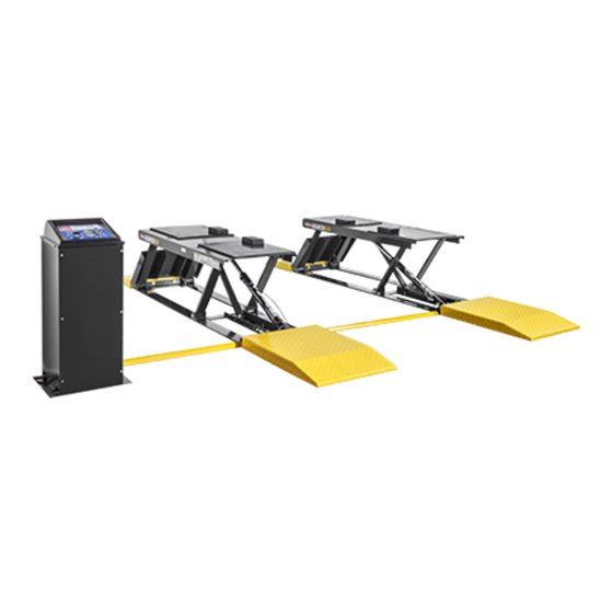
Installation and Operation Manual
Manual P/N 5900022 — Manual Revision B — November 2019
Models:
• P-9000LT
• P-9000LTF
Designed and engineered by BendPak Inc. in Southern California, USA. Made in China.
⚠
DANGER
Low-Rise Pit Lift
entire
Read the
contents of this manual
product. Failure to follow the instructions and safety precautions in
this manual can result in serious injury or death. Make sure all other
installers and operators also read this manual. Keep the manual
near the product for future reference. By proceeding with setup and
operation, you agree that you fully understand the contents.
1645 Lemonwood Dr.
Santa Paula, CA, 93060 USA
Toll Free (800) 253-2363
Tel: (805) 933-9970
bendpak.com
Model P-9000LT shown.
before
using this
Advertisement
Table of Contents

Related Manuals for BendPak P-9000LT


Summary of Contents for BendPak P-9000LT
- Page 1 Manual P/N 5900022 — Manual Revision B — November 2019 Models: • P-9000LT • P-9000LTF Model P-9000LT shown. Designed and engineered by BendPak Inc. in Southern California, USA. Made in China. ⚠ entire before Read the contents of this manual using this product.
- Page 2 Copyright. Copyright © 2019 by BendPak Inc. All rights reserved. You may make copies of this document if you agree that: you will give full attribution to BendPak Inc., you will not make changes to the content, you do not gain any rights to this content, and you will not use the copies for commercial purposes.
-
Page 3: Table Of Contents
Maintenance Log Introduction This manual describes the P-9000LT and P-9000LTF, which are low-rise, frame-engaging, pit lifts that are designed and engineered for fast-paced auto shop environments, oil-change facilities, and home garages. They can be installed at ground level or recessed (the F in P-9000LTF stands for “flush mount”), generally over a service pit. -
Page 4: Shipping Information
Replace any damaged or severely worn parts, decals, or warning labels. • BendPak recommends referring to the ANSI/ALI ALIS Standard Safety Requirements for Installation and Service for more information about safely installing, using, and servicing your Lift. P-9000LT/F Low-Rise Pit Lift... -
Page 5: Components
Hinged Ramps. • Hinged Ramps. Next to the Short Ramp while the P-9000LT/F is on the ground; hinges up when the Platforms are raised. • Platforms. Flat steel plates that raise and lower. Platforms have openings for the optional Lift Arms. - Page 6 Lift Arms. An optional accessory that provides additional raising capability for trucks and SUVs. Covers for Hydraulic, Return, and Air Lines included with Lift. Ramps shown in standard configuration: Short Ramps next to Hinged Ramps, Long Ramps on other side of Base. P-9000LT does not have Long or Short Ramps.
-
Page 7: Faqs
Q: The P-9000LTF is “flush mount”, what does that mean? A: It means the Bases of the P-9000LT/F are installed below the surface of the Concrete so that no Ramps are needed. Instead, the tops of the Platforms are flush with the Concrete when the Lift is fully lowered, so Vehicles just drive straight on to the Platforms. -
Page 8: Specifications
Specifications P-9000LT shown. The P-9000LT does not have Ramps or Covers. P-9000LT/F Low-Rise Pit Lift P/N 5900022 — Rev. B — Nov. 2019... - Page 9 * With supplied Hydraulic Hoses and Covers. ** 110 VAC units available on request. Lift loses ALI certification if used with a 110 VAC Power Unit. Specifications subject to change without notice. P-9000LT/F Low-Rise Pit Lift P/N 5900022 — Rev. B — Nov. 2019...
-
Page 10: Installation Checklist
Installation Checklist Following are the steps needed to install a P-9000LT/F Lift. Perform them in the order shown. ☐ 1. Review the installation Safety Rules. ☐ 2. Plan for Electrical Work. ☐ 3. Make sure you have the necessary Tools. -
Page 11: Installation
Installation This section describes how to install your P-9000LT/F. Perform the steps in the order listed. ⚠ Only use the factory-supplied parts that came with your Lift WARNING . If you use parts from a different source, you void your warranty and compromise the safety of everyone who installs or uses the Lift. - Page 12 Radial Shift. When you raise the Lift, the geometry of the scissor arms moves the Platforms up at an angle, towards the Hinged Ramp end. The amount of radial shift for the P-9000LT/F is approximately 12 in / 305 mm. Note that radial shift is always this direction, towards the Hinged Ramp end of the Lift, no matter which way the Vehicle is facing.
- Page 13 ~3 feet / ~1 meter is needed to the nearest obstruction on that end. P-9000LTF does not have Long or Short ramps. Not necessarily to scale. P-9000LT/F Low-Rise Pit Lift P/N 5900022 — Rev. B — Nov. 2019...
- Page 14 Regarding the distance between the two Frames: the P-9000LTF Frames can be from 36 to 42 before inches (914 to 1,066 mm) apart. You need to decide how far apart you want your Frames you create your Concrete Cutouts. BendPak strongly recommends consulting with your Concrete specialist before Important: creating your Concrete Cutouts.
- Page 15 If you create your Concrete Cutouts and then change your mind about the Distance NOTICE Between or find out you made a mistake with one of the numbers, it is very difficult double check your plan to fix. BendPak recommends you several times before pouring your Concrete Cutouts. P-9000LT/F Low-Rise Pit Lift...
- Page 16 Make sure to plan out, in advance, where the P-9000LT/F is going to go: • Clearance. If you are installing the P-9000LT/F over a pit, you are restricted as to where you can put it. Be sure to make sure there is adequate clearance on all sides.
- Page 17 When you raise the Lift, make sure to engage it on a Safety Lock. ⚠ WARNING BendPak strongly recommends using at least three people to lift the Platforms off the Bases: one person on each end to hold down the Base and one person to care operate the Forklift or Shop Crane to raise the Platform.
- Page 18 For example: • 4.75 in / 120 mm Anchor Bolts are stamped with a G. • 6.3 in / 160 mm Anchor Bolts are stamped with a J. P-9000LT/F Low-Rise Pit Lift P/N 5900022 — Rev. B — Nov. 2019...
- Page 19 Lift. The following drawing shows the locations of the six Anchor Bolt holes in each P-9000LT Base. Drawing not necessarily to scale. Not all components shown.
- Page 20 To anchor your Lift: 1. Make sure the Bases are in the correct location. Once the Anchor Bolts are torqued into position, they are not easily removed. BendPak strongly before recommends making sure the Bases are in the correct location anchoring them into place.
- Page 21 Anchor Bolts. Wrenching the Nut forces the wedge up, pushing out the Expansion Sleeve and pressing it tightly against the Concrete. P-9000LT/F Low-Rise Pit Lift P/N 5900022 — Rev. B — Nov. 2019...
- Page 22 Console. It is easier to change the Console location later if it is not anchored. When you want to anchor the Console into place, return to this section and follow the instructions starting with Step 8. P-9000LT/F Low-Rise Pit Lift P/N 5900022 — Rev. B — Nov. 2019...
- Page 23 11. Insert an Anchor Bolt with Washer into each hole, then tap it down into the hole. clockwise 12. Turn the Anchor Bolt to the recommended installation torque, 50 – 65 pound feet, using a Torque Wrench. P-9000LT/F Low-Rise Pit Lift P/N 5900022 — Rev. B — Nov. 2019...
- Page 24 Hydraulic Hoses to connect to the unit’s Hydraulic Cylinders, which is described in this section. 110 VAC Power Units are also available for the P-9000LT/F; these Power Units use a slightly different Hydraulic Hose setup, which is shown and...
- Page 25 9. Perform Steps 7 and 8 for the second Hydraulic Hose. 10. Make sure both Hydraulic Hoses are correctly routed and do not have any kinks, then use securely appropriate tools to tighten the finger-tightened connections. P-9000LT/F Low-Rise Pit Lift P/N 5900022 — Rev. B — Nov. 2019...
- Page 26 Hydraulic Hoses. If you ordered a 110 VAC Power Unit with the P-9000LT/F, then the Lift came with one Short Hydraulic Hose and two Long Hydraulic Hoses. These should be configured as shown below. Fittings shown not connected for clarity. Drawing not to scale.
- Page 27 , remove the Shipping Plugs from the Hydraulic Hose Ports near the bottom of each Hydraulic Cylinder. 9. Attach an Hydraulic Elbow Fitting to each of the Hydraulic Hose Ports. P-9000LT/F Low-Rise Pit Lift P/N 5900022 — Rev. B — Nov. 2019...
- Page 28 Finger tighten the connections. 12. Make sure both Hydraulic Hoses are correctly routed and do not have any kinks, then use appropriate tools to securely tighten the finger-tightened connections. P-9000LT/F Low-Rise Pit Lift P/N 5900022 — Rev. B — Nov. 2019...
- Page 29 The Ferrule goes around the Rod and under the Threads. The Nut goes onto the Threads. 6. Tighten the Nut. Remember that the Ferrule can only be used once; do not tighten the Nut until everything is ready. P-9000LT/F Low-Rise Pit Lift P/N 5900022 — Rev. B — Nov. 2019...
- Page 30 2. Locate the black plastic Tubing and one Tee Compression Fitting. 3. Cut the Tubing into appropriate lengths for your installation. BendPak recommends planning out the path of the Air Line before you start cutting the Tubing. 4. Connect the Tubing lengths and the Tee Compression Fitting to the Compression Fittings on the Air Cylinders.
- Page 31 Air Line Pipe Fitting. Pushbutton is above the Console Cover, all other components are under the Console Cover. Drawing not necessarily to scale. Not all components shown. P-9000LT/F Low-Rise Pit Lift P/N 5900022 — Rev. B — Nov. 2019...
- Page 32 4. Take the Top Nut off of the threads on the Microswitch. 5. Put the Microswitch and Lower Nut into place through the Console Cover. The Microswitch is the Raise button. P-9000LT/F Low-Rise Pit Lift P/N 5900022 — Rev. B — Nov. 2019...
- Page 33 Mini Switch. 13. Turn the Console Cover right side up, then secure it in place. P-9000LT/F Low-Rise Pit Lift P/N 5900022 — Rev. B — Nov. 2019...
- Page 34 4. Locate the Return Line Tubing. 5. Cut Tubing sections of the appropriate length for each of the three Return Line segments. 6. Connect the three Tubing sections between the Fittings. P-9000LT/F Low-Rise Pit Lift P/N 5900022 — Rev. B — Nov. 2019...
- Page 35 The standard Power Unit for the P-9000LT/F is 208-240 VAC, 50/60 Hz, 1 phase. Power Units are provided by different vendors. There may be minor differences in look and feel between them;...
- Page 36 High running amps that exceed the motor’s full load amps (FLA) rating may result in permanent Do not exceed the rated duty cycle of the motor. damage to the motor. P-9000LT/F Low-Rise Pit Lift P/N 5900022 — Rev. B — Nov. 2019...
- Page 37 Hydraulic Fluid leaks, slow operation, and so on. strongly Your Lift is shipped from the factory with clean components; however, BendPak recommends that you give the hydraulic components an extra cleaning. Even a small grain of debris introduced into the Hydraulic System is enough to make the Lift unusable.
- Page 38 Reservoir. Important: The Power Units currently shipping with the P-9000LT/F hold approximately 1.5 gallons / 5.5 liters of Hydraulic Fluid. If different Power Units are substituted in the future, which occasionally happens, you could end up with a Power Unit with a different sized Hydraulic Fluid Reservoir.
- Page 39 If the Lift is shaking, moving erratically, or squeaking, repeat the procedure one more time, this time with a Vehicle on the Lift. If you continue to have issues, refer to Troubleshooting for assistance. P-9000LT/F Low-Rise Pit Lift P/N 5900022 — Rev. B — Nov. 2019...
- Page 40 • Leave the Installation and Operation Manual with the owner/operator. It needs to be available to anyone who operates, maintains, or troubleshoots the Lift. P-9000LT/F Low-Rise Pit Lift P/N 5900022 — Rev. B — Nov. 2019...
-
Page 41: Operation
Safety First BendPak strongly recommends referring to the ANSI/ALI ALIS Standard Safety Requirements for Installation and Service for more information about safely using your Lift. Before you raise or lower a Vehicle using your Lift, do the following: •... - Page 42 • Raise button. Moves the Platforms up. • Lower button. Moves the Platforms down, either all of the way down to the ground or onto a Safety Lock. P-9000LT/F Low-Rise Pit Lift P/N 5900022 — Rev. B — Nov. 2019...
- Page 43 Safety Locks, the weight of the Vehicle holds the Platforms in place. If the power goes out or the Hydraulic Hoses are cut or start to leak, the Safety Lock holds the P-9000LT Platforms, and anything on them, in place.
- Page 44 (you may need to lower the Vehicle some to adjust the Lift Blocks). 9. After confirming the Lift Blocks are properly positioned, press Raise. The Platforms start going up again and the Lift Blocks contact the Vehicle’s Lifting Points. P-9000LT/F Low-Rise Pit Lift P/N 5900022 — Rev. B — Nov. 2019...
- Page 45 Lower button and immediately evacuate the area. If safe to do so, return to the Console and carefully lower the Platforms back down to the ground. 4. When the Platforms are fully lowered, release both buttons. P-9000LT/F Low-Rise Pit Lift P/N 5900022 — Rev. B — Nov. 2019...
-
Page 46: Lift Arm Kit
The Lift Arms increase the capabilities of your Lift. The pads and extenders let you quickly and easily hit the lifting points of cars, light trucks, and SUVs. If you are using your P-9000LT/F in a pit environment, the Lift Arms install over your pit without interfering with your lube bay opening. - Page 47 Never move the inside edges of the Lift Arms past the corners of the Platform. They are not designed to hold weight past the inside edges; you could damage the Lift or the Lift Arms. P-9000LT/F Low-Rise Pit Lift P/N 5900022 — Rev. B — Nov. 2019...
-
Page 48: Maintenance
DANGER cannot from power and be re-energized until all maintenance is complete. BendPak strongly recommends using your Power Disconnect Switch during maintenance. The Lift uses electrical and pneumatic energy; if your organization has before Lockout/Tagout policies, implement them performing any maintenance. -
Page 49: Troubleshooting
• Use a lifting device to raise the Vehicle up four inches or higher. If you are still unable to raise your Vehicle, contact BendPak Technical Support for assistance. P-9000LT/F Low-Rise Pit Lift P/N 5900022 — Rev. B — Nov. 2019... -
Page 50: Wiring Diagrams
Wiring Diagrams 5585020 5585015 P-9000LT/F Low-Rise Pit Lift P/N 5900022 — Rev. B — Nov. 2019... - Page 51 WARNING: must be done by a licensed, certified Electrician Cord, in accordance with all applicable local electrical codes. Damage caused by improper electrical installation may void your warranty. P-9000LT/F Low-Rise Pit Lift P/N 5900022 — Rev. B — Nov. 2019...
-
Page 52: Labels
Labels P-9000LT/F Low-Rise Pit Lift P/N 5900022 — Rev. B — Nov. 2019... - Page 53 P-9000LT/F Low-Rise Pit Lift P/N 5900022 — Rev. B — Nov. 2019...
- Page 54 P-9000LT/F Low-Rise Pit Lift P/N 5900022 — Rev. B — Nov. 2019...
-
Page 55: Parts Diagrams
Parts Diagrams P-9000LT/F Low-Rise Pit Lift P/N 5900022 — Rev. B — Nov. 2019... - Page 56 P-9000LT/F Low-Rise Pit Lift P/N 5900022 — Rev. B — Nov. 2019...
- Page 57 P-9000LT/F Low-Rise Pit Lift P/N 5900022 — Rev. B — Nov. 2019...
- Page 58 P-9000LT/F Low-Rise Pit Lift P/N 5900022 — Rev. B — Nov. 2019...
- Page 59 P-9000LT/F Low-Rise Pit Lift P/N 5900022 — Rev. B — Nov. 2019...
- Page 60 P-9000LT/F Low-Rise Pit Lift P/N 5900022 — Rev. B — Nov. 2019...
- Page 61 P-9000LT/F Low-Rise Pit Lift P/N 5900022 — Rev. B — Nov. 2019...
- Page 62 P-9000LT/F Low-Rise Pit Lift P/N 5900022 — Rev. B — Nov. 2019...
-
Page 63: Maintenance Log
Maintenance Log P-9000LT/F Low-Rise Pit Lift P/N 5900022 — Rev. B — Nov. 2019... - Page 64 1645 Lemonwood Drive Santa Paula, CA 93060 USA © 2019 by BendPak Inc. All rights reserved. bendpak.com...
Need help?
Do you have a question about the P-9000LT and is the answer not in the manual?
Questions and answers