Table of Contents
Advertisement
Quick Links
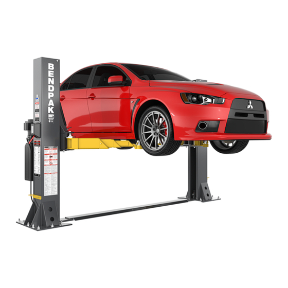
Short-Column
Installation and Operation Manual
Models:
• 10AP-SRT
• 12AP-SRT
Original Instructions in
the English language.
Designed and engineered by BendPak Inc. in Southern California, USA. Made in China.
I
S
MPORTANT
AFETY
contents of this manual before using this product. Failure to follow the instructions and safety
precautions in this manual can result in severe injury or death. Make sure all other operators also read
this manual. Keep the manual near the product for future reference.
operation, you agree that you fully understand the contents of this manual and assume full
responsibility for product use
10AP-SRT/12AP-SRT
Short-Rise
,
Manual P/N 5900354 — Manual Revision B1 — June 2024
⚠
DANGER
I
, S
NSTRUCTIONS
.
Two-Post Lift
,
T
I
AVE
HESE
NSTRUCTIONS
30440 Agoura Road
Agoura Hills, CA 91301 USA
Telephone: (805) 933-9970
! Read the entire
By proceeding with setup and
bendpak.com
Advertisement
Table of Contents


Need help?
Do you have a question about the 10AP-SRT and is the answer not in the manual?
Questions and answers