Table of Contents
Advertisement
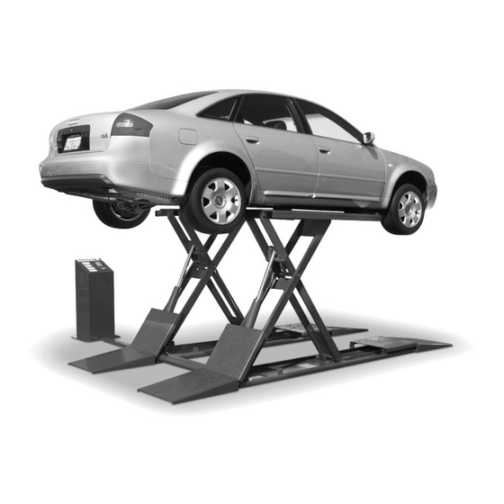
7,000 POUND CAPACITY
FULL-RISE
SCISSORS LIFT
MODEL: SP-7X
SHIPPING DAMAGE CLAIMS
When this equipment is shipped, title passes to the
purchaser upon receipt from the carrier.
Consequently, claims for the material damaged in ship-
ment must be made by the purchaser against the trans-
portation company at the time shipment is received.
PLEASE READ THE ENTIRE CONTENTS OF THIS MANUAL PRIOR TO
INSTALLATION AND OPERATION. BY PROCEEDING YOU AGREE THAT
YOU FULLY UNDERSTAND AND COMPREHEND THE FULL CONTENTS OF
THIS MANUAL. FORWARD THIS MANUAL TO ALL OPERATORS. FAILURE TO
OPERATE THIS EQUIPMENT AS DIRECTED MAY CAUSE INJURY OR DEATH.
INSTALLATION AND OPERATION MANUAL
INSTALLATION AND OPERATION MANUAL
Keep this operation manual near the
machine at all times. Make sure that
ALL USERS read this manual.
BE SAFE
Your new lift was designed and built with safety in mind.
However, your overall safety can be increased by proper
training and thoughtful operation on the part of the
operator. DO NOT operate or repair this equipment with-
out reading this manual and the important safety instruc-
tions shown inside.
1
REV C 08-20-089
p/n 5900109
1645 Lemonwood Dr.
Santa Paula, CA. 93060, USA
Toll Free 1-800-253-2363
Tel: 1-805-933-9970
Fax: 1-805-933-9160
www.bendpak.com
Advertisement
Table of Contents

Related Manuals for BendPak SP-7X


Summary of Contents for BendPak SP-7X
- Page 1 5900109 INSTALLATION AND OPERATION MANUAL INSTALLATION AND OPERATION MANUAL 7,000 POUND CAPACITY FULL-RISE SCISSORS LIFT MODEL: SP-7X Keep this operation manual near the machine at all times. Make sure that ALL USERS read this manual. BE SAFE SHIPPING DAMAGE CLAIMS Your new lift was designed and built with safety in mind.
- Page 2 BendPak Inc. shall repair or replace at their option for the warranty period those parts returned to the factory freight prepaid which prove upon inspection to be defective. BendPak Inc. will pay labor costs for the first 12 months only on parts returned as previously described.
-
Page 3: Definitions Of Hazard Levels
Our willingness to product or property damage. assist in helping you process your claim does not make BendPak responsible for collection of claims or replace- ment of lost or damaged materials. -
Page 4: Table Of Contents
TABLE OF CONTENTS Contents Page No. Warranty / Serial Number Information ..............2 Definitions of Hazard Levels . -
Page 5: Installer / Operator Agreement / Protective Equipment
I understand that BendPak lifts are designed to be and operation activities. installed in indoor locations only. Failure to follow instal-... - Page 6 INTRODUCTION Carefully remove the crating and packing Check the voltage, phase and proper amperage materials. CAUTION! Be careful when cutting steel requirements for the motor shown on the motor plate. banding material as items may become loose and fall Wiring should be performed by a certified electrician causing personal harm or injury.
-
Page 7: Tools Required
TOOLS REQUIRED Rotary Hammer Drill or Similar Medium Crescent Wrench 3/4” Masonry Bit Medium Pipe Wrench Hammer Crow Bar 4 Foot Level Chalk Line Open-End Wrench Set: SAE/Metric Medium Flat Screwdriver Socket And Ratchet Set: SAE/Metric Tape Measure: 25 Foot Minimum Hex-Key / Allen Wrench Set Needle Nose Pliers NOTE:... - Page 8 When removing the lift from shipping angles or pallets pay close attention as the lift can slide and can cause injury. Prior to removing the lift make sure the lift is held securely by a fork lift or some other heavy lifting device. PARTS INVENTORY Be sure to take a complete inventory of parts prior to beginning installation.
- Page 9 FLOORPLAN / LAYOUT DIMENSIONS...
- Page 10 STEP THREE Fig. 3.3 ( Anchoring The Lift Frames ) 1. The lift can be installed with the BOLSTER BAR ( the round bar connecting the frames together ) located either at the front or rear. Typical installations place the Bolster Bar at the rear to allow for unobstructed work space underneath the engine compartment and to allow for rolling oil drains or other shop equipment.
-
Page 11: Step 4 / Power Console / Hose Routing
STEP FOUR 6. Connect the Power Unit Hose to the Straight Fitting on the Flow Divider and connect both the Powerside and ( Power Console / Hose Routing ) Offside Hydraulic Hoses to the 90° Fittings on the Flow divider as shown. (See Fig. 4.4) 1. - Page 12 2. Route the two Hydraulic Hoses through the hole at the Powerside of the Lift Frame and connect the Powerside (medium) Hose to the 90° Fitting of the Powerside Cylinder. (See Fig. 5.2) DO NOT use Tefl on tape or other sealant on JIC fi...
-
Page 13: Step 6 / Power Unit Hook Up
STEP SIX ( Power Unit Hook Up ) DANGER ! ALL WIRING MUST BE PERFORMED RISK OF EXPLOSION! BY A LICENSED ELECTRICIAN. This equipment has internal arcing or parts that may spark and should not be exposed to fl ammable vapors. Motor should not be located in a recessed area or below fl... - Page 14 STEP SEVEN POST-INSTALLATION CHECK-OFF ( Lift Start Up ) Columns Properly Shimmed And Stable Anchor Bolts Tightened Pivot / Sheave Pins Properly Attached Carriage Stop bolts Torqued to 20 Ft. Lbs CAUTION! Electric Power Supply Confirmed During the START-UP procedure, observe all Cables Adjusted Properly operating components and check for proper installation Safety Locks Functioning Properly...
- Page 15 STEP 8 (Operation) To Raise Lift; 1. Load vehicle onto the lift using Vehicle Lifting Guide to determine proper lifting points. 2. NEVER use lift pad assemblies without rubber slip over pads in place. 3. Set parking brake or use wheel chock to hold vehicle in position.
- Page 16 TO RAISE LIFT Read operating and Safety manuals before using lift. Always lift a vehicle according to the manufactures recommended lifting points. Position vehicle properly. Insure that the vehicle is positioned with the center of gravity midway between pads. NEVER use runway assemblies without rubber pads in place. Raise the vehicle by depressing button until the vehicle just lifts off the ground.
-
Page 19: Step 8 / Lift Operation
Safe Lift Operation Automotive and truck lifts are critical to the operation and profitability of your business. The safe use of this and other lifts in your shop is critical in preventing employee injuries and damage to customer’s vehicles. By operating lifts safely you can insure that your shop is profitable, productive and safe. - Page 20 DO NOT leave the controls while the lift is still in motion. DO NOT stand directly in front of the vehicle or in the bay when vehicle is being loaded or driven into position. DO NOT Go near vehicle or attempt to work on the vehicle when being raised or lowered. REMAIN CLEAR of lift when raising or lowering vehicle.
- Page 21 LIFT WILL NOT RAISE POSSIBLE CAUSE 1. Air in oil, (1,2,8,13) 2. Cylinder binding, (9) 3. Cylinder leaks internally, (9) 4. Motor run backward under pressure, (11) 5. Lowering valve leaks, (3,4,6,10,11) 6. Motor runs backwards, (7,14,11) 7. Pump damaged, (10,11) 8.
- Page 22 MOTOR WILL NOT RUN POSSIBLE CAUSE Fuse blown, (5,2,1,3,4) Limit switch burned out, (1,2,3,4) Microswitch burned out, (1,2,3,4) Motor burned out, (1,2,3,4,6) Voltage to motor incorrect, (2,1,8) REMEDY INSTRUCTION Check for correct voltage ......Compare supply voltage with voltage on motor nametag.
- Page 23 WILL NOT RAISE LOADED LIFT POSSIBLE CAUSE 1. Air in oil, (1,2,3,4) 2. Cylinder binding, (5) 3. Cylinder leaks internally, (5) 4. Lift overloaded, (6,5) 5. Lowering valve leaks, (7,8,1,5,9) 6. Motor runs backwards, (10,12,9) 7. Pump damaged, (5,9) 8. Pump won’t prime, (1,2,3,4,5,11,9) 9.
- Page 24 LIFT WILL NOT STAY UP POSSIBLE CAUSE 1. Air in oil, (1,2,3) 2. Check valve leaks, (6) 3. Cylinders leak internally, (7) 4. Lowering valve leaks, (4,5,1,7,6) 5. Leaking fittings, (8) REMEDY INSTRUCTION 1. Check oil level ........The oil level should be up to the bleed screw in the reservoir with the lift all the way down.
-
Page 25: Maintenance Records
MAINTENANCE RECORDS ____________________________________________________________________ ____________________________________________________________________ ____________________________________________________________________ ____________________________________________________________________ ____________________________________________________________________ ____________________________________________________________________ ____________________________________________________________________ ____________________________________________________________________ ____________________________________________________________________ ____________________________________________________________________ ____________________________________________________________________ ____________________________________________________________________ ____________________________________________________________________ ____________________________________________________________________ ____________________________________________________________________ ____________________________________________________________________ ____________________________________________________________________ ____________________________________________________________________ ____________________________________________________________________ ____________________________________________________________________... - Page 30 For Parts Or Service Contact: BendPak Inc. / Ranger Products 1645 Lemonwood Dr. Santa Paula, CA. 93060 Tel: 1-805-933-9970 Toll Free: 1-800-253-2363 Fax: 1-805-933-9160 www.bendpak.com www.rangerproducts.com p/n 5900109...
Need help?
Do you have a question about the SP-7X and is the answer not in the manual?
Questions and answers