BendPak XPR-10S Installation And Operation Manual
10,000 lb /4536 kg capacity
surface mounted two-post lifts
Hide thumbs
Also See for XPR-10S:
- Installation and operation manual (92 pages) ,
- Service manual (46 pages)
Table of Contents
Advertisement
EUROPEAN USERS
400V 50Hz SUPPLY DETAILS ARE
INCLUDED WITH ELECTRICAL
CONTROL BOX. DISREGARD SUPPLY
WIRING DETAILS IN THIS MANUAL
10,000 LB /4536 KG CAPACITY
SURFACE MOUNTED TWO-POST LIFTS
MODELS:
XPR-10S
XPR-10S-LP
XPR-10S-168
XPR-10S-168-LP
XPR-10TS
XPR-10TS-168
XPR-10AS
XPR-10AS-LP
XPR-10AS-168
XPR-10AS-168-LP
ORIGINAL INSTRUCTIONS IN
ENGLISH LANGUAGE
RECEIVING
The shipment should be thoroughly inspected as soon as it
is received. The signed Bill of Lading is acknowledgement
by the shipping carrier as receipt of this product as listed
in your invoice as being in a good condition of shipment. If
any of these goods listed on this Bill of Lading are missing
or damaged, do not accept goods until the shipping carrier
makes a notation on the freight bill of the missing or
damaged goods. Do this for your own protection.
PLEASE READ THE ENTIRE CONTENTS OF THIS MANUAL PRIOR TO
INSTALLATION AND OPERATION. BY PROCEEDING WITH LIFT INSTALLATION
AND OPERATION YOU AGREE THAT YOU FULLY UNDERSTAND THE
FULL CONTENTS OF THIS MANUAL. FORWARD THIS MANUAL TO ALL
OPERATORS. FAILURE TO OPERATE THIS EQUIPMENT AS DIRECTED MAY
CAUSE INJURY OR DEATH.
INSTALLATION AND OPERATION MANUAL
IMPORTANT SAFETY INSTRUCTIONS
SAVE THESE INSTRUCTIONS
BE SAFE
Your new lift was designed and built with safety in mind.
However, your overall safety can be increased with proper
training and thoughtful operation on the part of the operator.
DO NOT operate or repair this equipment without reading
this manual and the important safety instructions shown
inside. Keep this operation manual near the lift at all times.
Make sure that ALL USERS read and understand this
manual.
1
MAN REV A 09-06-2016
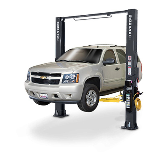
Symmetrical
.
model shown
Keep this operation manual near the
machine at all times. Make sure that
ALL USERS read this manual.
1645 Lemonwood Dr.
Santa Paula, CA. 93060, USA
Toll Free 1-800-253-2363
Tel: 1-805-933-9970
Fax: 1-805-933-9160
www.bendpak.com
P/N 5900951
Advertisement
Table of Contents

Related Manuals for BendPak XPR-10S


Summary of Contents for BendPak XPR-10S
- Page 1 CONTROL BOX. DISREGARD SUPPLY WIRING DETAILS IN THIS MANUAL CAUSE INJURY OR DEATH. MAN REV A 09-06-2016 P/N 5900951 INSTALLATION AND OPERATION MANUAL 10,000 LB /4536 KG CAPACITY SURFACE MOUNTED TWO-POST LIFTS MODELS: XPR-10S XPR-10S-LP XPR-10S-168 XPR-10S-168-LP XPR-10TS XPR-10TS-168 XPR-10AS XPR-10AS-LP XPR-10AS-168...
-
Page 2: Warranty / Serial Number Information
Our comprehensive product warranty means more than a commitment to you; it’s also a commitment to the value of your new BendPak lift. For full warranty details and to register your new lift contact your nearest BendPak dealer or visit: http:/ / www.bendpak.com/ support/ warranty/... -
Page 3: Definitions Of Hazard Levels
Our willingness to practices which may result in minor personal injury, assist in helping you process your claim does not make product or property damage. BendPak responsible for collection of claims or replacement of lost or damaged materials. -
Page 4: Table Of Contents
TABLE OF CONTENTS Warranty / Serial Number Information ............. . 2 Definitions of Hazard Levels . -
Page 5: Installer/Operator Agreement/ Protective Equipment
I understand that Bendpak lifts are designed to be Eye protection is essential during installed in indoor locations only. Failure to follow installation and operation activities. -
Page 6: Introduction
INTRODUCTION 1. Carefully remove the crating and packing 2. Check the voltage, phase and proper amperage materials. CAUTION! Be careful when cutting steel requirements for the motor shown on the motor plate. banding material as items may become loose and fall Wiring should be performed by a certified electrician only. -
Page 7: Tools Required
IMPORTANT NOTE BendPak lifts are supplied with installation instructions and concrete fasteners meeting the criteria as prescribed by the American National Standard "Automotive Lifts - Safety Requirements for Construction, Testing, and Validation" ANSI/ALI ALCTV-2011. Lift buyers are responsible for any special regional structural and/or seismic anchoring requirements specified... -
Page 8: Assembly View / Description Of Parts
When removing the lift from shipping angles, pay close attention as the posts can slide and can cause injury. Prior to removing the bolts make sure the posts are held securely by a fork lift or some other heavy lifting device. PARTS INVENTORY Be sure to take a complete inventory of parts prior to beginning installation. -
Page 9: Floor Plan
FLOOR PLAN MODEL XPR-10S XPR-10TS XPR-10S-LP Lifting Capacity 10,000Lbs. / 4536Kg. 10,000Lbs. / 4536Kg. 10,000Lbs. / 4536Kg. Max Capacity/ Front Axle 5,000Lbs. / 2268Kg. 5,000Lbs. / 2268Kg. 5,000Lbs. / 2268Kg. Max Capacity/ Rear Axle 5,000Lbs. / 2268Kg. 5,000Lbs. / 2268Kg. - Page 10 FLOOR PLAN MODEL XPR-10S-168 XPR-10TS-168 XPR-10S-168-LP Lifting Capacity 10,000Lbs. / 4536Kg. 10,000Lbs. / 4536Kg. 10,000Lbs. / 4536Kg. Max Capacity/ Front Axle 5,000Lbs. / 2268Kg. 5,000Lbs. / 2268Kg. 5,000Lbs. / 2268Kg. Max Capacity/ Rear Axle 5,000Lbs. / 2268Kg. 5,000Lbs. / 2268Kg.
- Page 11 FLOOR PLAN NOTE: Power Unit MUST go only where X is located. MODEL XPR-10AS XPR-10AS-168 XPR-10AS-LP XPR-10AS-168-LP 10,000Lbs. / 4536Kg. 10,000Lbs. / 4536Kg. 10,000Lbs. / 4536Kg. 10,000Lbs. / 4536Kg. Lifting Capacity Max Capacity/ Front Axle 5,000Lbs. / 2268Kg. 5,000Lbs. / 2268Kg. 5,000Lbs.
-
Page 12: Clearances
CLEARANCES XPR-10S LIFT HEIGHT CLEARANCE NOTE: There must be a 1” MIN distance from top of lift to nearest obstruction. -
Page 13: Clearances
CLEARANCES XPR-10AS LIFT HEIGHT CLEARANCE NOTE: There must be a 1” MIN. distance from top of lift to nearest obstruction. -
Page 14: Step 3 / Post Preparation
STEP 3 NOTE: (Post Preparation) SYMMETRICAL MODELS BOTH CABLES ARE SAME COMPLETE THE FOLLOWING LENGTH. ASYMMETRIC MODELS HAVE TWO PRIOR TO RAISING THE POSTS DIFFERENT LENGTH CABLES. (SEE FIG. 3.4) Fig 3.4 NOTE: Short cable on lock plate DETERMINE DESIRED LOCATION AND WIDTH THIS SIDE LAYOUT BEFORE RAISING POSTS. - Page 15 5. Install the cylinder fittings in cylinder ports. Pay attention NOTE FOR EXTENDED HEIGHT MODELS: when installing the fittings to ensure that each fitting points FOR XPR-10S-168, XPR-10AS-168, XPR-10TS-168, towards the side of the post that the hose retainer clips are XPR-10S-168-LP, XPR-10AS-LP-168 MODELS, FIT located on.
-
Page 16: Equalizer Cable Routing
EQUALIZER CABLE ROUTING SHORT CABLE (“A” Models) LONG CABLE (“A” Models) THREADED END BUTTON END OFFSIDE POWERSIDE XPR-10AS wide configuration shown. NOTE: XPR -10S models: both Equalizer Cables are the same length. Overhead Assembly sheaves ARE NOT staggered. XPR-10AS models: have one short and one long Equalizer Cable. Overhead Assembly sheaves ARE staggered. -
Page 17: Hose Routing
HOSE ROUTING... -
Page 18: Step 4 / Site Layout
Fig 4.1 CHALK LINE FOR XPR-10S CONFIGURATIONS USE BASE PLATE EDGES TO ALIGN POSTS. CHALK LINE FOR XPR-10AS CONFIGURATIONS USE NOTCHES TO ALIGN POSTS. STEP 4 STEP 5 (Site Layout) (Installing the POWER SIDE post) 1. Determine which side of the lift will be the approach side. -
Page 19: Step 6 / Installing Off Side Post
2. Using the baseplate on the POWER SIDE post as a NOTE: guide, drill each anchor hole in the concrete approximately 4” deep for 10K models using a rotary hammer drill and 3/4” TO EASE INSTALLATION OF THE OVERHEAD concrete drill-bit. To ensure full holding power, do not ream ASSEMBLY, IT HELPS TO KEEP THE ANCHOR the hole or allow the drill to wobble. -
Page 20: Step 8 / Mounting The Hydraulic Power Unit
STEP 8 Fig 7.1 Narrow Configuration (Mounting the Hydraulic Power Unit) 1. Attach the power unit to the POWER SIDE post. Install the vibration dampener between the power unit and the power unit mounting plate on the Power Side post, using four M8 hex head bolts and nuts supplied. - Page 21 DO NOT RUN POWER UNIT WITHOUT OIL. DAMAGE TO POWER UNIT PUMP CAN OCCUR. THE POWER UNIT MUST BE KEPT DRY. DAMAGE TO POWER UNIT CAUSED BY WATER OR OTHER LIQUIDS SUCH AS DETERGENTS, ACID ETC., IS NOT COVERED UNDER WARRANTY. OPERATE LIFT ONLY BETWEEN TEMPERATURES OF 41 °- 104°...
- Page 22 XPR-10S Models NOTE: Top plate cut away for clarity Safety Cable ENSURE THAT BOTH THE POWER SIDE & OFF SIDE SAFETIES ENGAGE PROPERLY PRIOR TO LIFT OPERATION. Fig 9.3 Insert non-looped end of safety cable through Fig 9.5 hole in post...
-
Page 23: Step 10 / Installing Hydraulic Lines
STEP 10 3. Route the Off Side cylinder hose (Crossover Hose) (Installing Hydraulic Lines) up through the post and across the Overhead Assembly, down the post and connect it to the bulkhead tee fitting. FOR WIDE CONFIGURATION, A 13” EXTENSION (See Fig 10.1 and Fig 10.2) FOR SYMMETRIC MODELS OR AN 8”... -
Page 24: Step 12 / Installing Overhead Microswitch
STEP 12 until taut, checking that both cables have equal tension. (See Fig 11.3) (Installing Overhead Microswitch) Equalizer Cables XPR-10AS Short Cable Here MICROSWITCH WIRE MUST BE RUN THROUGH CLIPS IN POST AND OVERHEAD ASSEMBLY. FAILURE TO DO SO CAN CAUSE DAMAGE TO LIFT OR TO VEHICLES. -
Page 25: Step 13 / Installing Power Unit Hose Assembly And Power Side Safety Cover
3. Route wire up through post and across Overhead 2. Install the 90° fitting w/ O-ring into the power port of Assembly through hole in Overhead Assembly into the the power unit. Use Teflon tape on the pipe fittings ONLY. Microswitch box. -
Page 26: Step 14 / Installing The Lift Arms
THE ARM RESTRAINT GEARS MUST BE POSITIONED PROPERLY. CONFIRMATION OF PROPER GEAR ENGAGEMENT MUST BE MADE PRIOR TO THE OPERATION OF THE LIFT. PERIODIC INSPECTION IS REQUIRED. FAILURE Screw TO INSPECT THE ARM RESTRAINT GEARS ON ALL FOUR ARMS PROPERLY CAN RESULT IN DAMAGE TO THE VEHICLE OR INJURY AND/OR DEATH. - Page 27 FUNCTIONING PROPERLY. REPLACE ANY BROKEN COMPONENTS OR COMPONENTS WITH BROKEN TEETH ONLY WITH AUTHORIZED OR APPROVED REPLACEMENT PARTS. Fig. 14.7 XPR-10S/TS: Triple Telescoping Arm Assembly XPR-10S-LP: Medium Arm Assembly Approach XPR-10S/LP: Medium Arm Assembly XPR-10TS: Triple Telescoping Arm As- sembly Fig.
- Page 29 YOU MUST RE-INSTALL TOP CARRIAGE-STOP BOLT (SHOWN BELOW). TIGHTEN CARRIAGE-STOP BOLT TO 2-3 FT.-LBS. OF TORQUE UPON FINAL INSTALLATION INSPECTION. THESE INSTRUCTIONS MUST BE FOLLOWED TO ENSURE PROPER INSTALLATION AND OPERATION OF YOUR LIFT. FAILURE TO COMPLY WITH THESE INSTRUCTIONS CAN RESULT IN SERIOUS BODILY INJURY AND/OR DEATH AND/OR VOID PRODUCT WARRANTY.
-
Page 30: Step 15 / Power Unit Connection
DO NOT PERFORM ANY MAINTENANCE OR INSTALLATION OF ANY COMPONENTS WITHOUT FIRST ENSURING THAT ELECTRICAL POWER HAS BEEN DISCONNECTED AT THE SOURCE OR PANEL AND CANNOT BE RE-ENERGIZED UNTIL ALL MAINTENANCE AND/OR INSTALLATION PROCEDURES ARE COMPLETED. IMPORTANT POWER-UNIT INSTALLATION NOTES n DO NOT run power unit without oil. -
Page 32: Step 16 / Lift Start Up Final Adjustments
STEP 16 STEP 15 (Lift Start Up / Final Adjustments) (Power Unit Connection) 1. Have a certified electrician run the power supply to motor. Refer to the data plate found on the motor for proper power supply and wire size. DURING THE START-UP PROCEDURE, OBSERVE ALL OPERATING COMPONENTS AND CHECK FOR PROPER INSTALLATION AND ADJUSTMENT. -
Page 33: Post Installation Checklist
POST-INSTALLATION CHECK-OFF NOTE: THERE WILL BE INITIAL STRETCHING OF THE CABLES AND/OR WITH INCREASED LOADS. n Columns properly shimmed and stable. ADJUST THE CABLES AS OUTLINED ABOVE A n Anchor Bolts tightened. WEEK AFTER FIRST USE, THEN EVERY THREE n Pivot / Sheave Pins properly attached. TO SIX MONTHS THEREAFTER DEPENDING ON n Electric power supply confirmed. -
Page 34: Optional Equipment Installation / Optional Accessories
OPTIONAL EQUIPMENT INSTALLATION... - Page 35 OPTIONAL AND STANDARD ACCESSORIES Optional Equipment available through your Authorized BendPak Dealer. Telescoping Screw Pad Frame Cradle Pad...
- Page 36 If the lift was provided with Lift Arm Foot Guards, install the shorter Foot Guard on the shorter Arm Assembly and the longer Foot Guard on the longer Arm Assembly. To install, firmly squeeze the ends of the Foot Guard inwards and insert the ends underneath the bent ends of the arm support.
-
Page 37: Step 19 / Operation/ Maintenance
• ALWAYS keep area around lift free of tools, debris, or if it has broken or damaged parts. Use only qualified grease and oil. lift service personnel and genuine BendPak parts to make repairs. • NEVER overload lift. Capacity of lift is shown on nameplate affixed to the lift. - Page 38 LIFT OPERATION SAFETY (CONT’D) • ALWAYS load vehicle on lift carefully. Position the lift adapters to contact at the vehicle manufacturer’s recommended lift points. Raise lift until adapters contact vehicle. Check adapters for secure contact with vehicle. Raise lift to desired working height. (See Fig.19.1) WHEN LOWERING THE LIFT PAY CAREFUL ATTENTION THAT ALL PERSONNEL AND OBJECTS ARE KEPT CLEAR.
- Page 39 FAILURE TO COMPLY MAY CAUSE MOTOR BURNOUT. to the VEHICLE CENTER OF BALANCE instructions found on our website at: www.bendpak.com/support/balancing-safety/ 4. Position vehicle for proper weight distribution arms under vehicle to allow adapters to contact at the manufacturer’s recommended pick up points.
- Page 40 LIFT OPERATION SAFETY (CONT’D) 6. Push the RAISE button or rotate the control switch on the power unit. Stop before making contact with vehicle. Check arm restraint pins for engagement. If required, slightly move WHEN LOWERING THE LIFT PAY CAREFUL arm to allow restraint gear and pawl to mesh.
- Page 41 Reorder labels • Daily: Check cables and sheaves for wear. Replace from BendPak. worn parts as required with genuine BendPak parts. • Refer to ANSI/ALI ALOIM booklet for periodic • Daily: Inspect adapters for damage or excessive inspection checklist and maintenance log sheet.
- Page 42 TO RAISE LIFT Read operating and safety manuals before using lift. Always lift a vehicle according to the manufacturers recommended lifting points. Position vehicle between posts. Adjust swing arms so that the vehicle is positioned with the center of gravity midway between pads. Use truck adapters as needed.
- Page 43 WIRE ROPE INSPECTION AND MAINTENANCE Lifting cables should be replaced every three - five years or when visible signs of damage are apparent. DO NOT USE LIFT WITH DEFECTIVE / WORN CABLES. Lifting cables should be maintained in a well-lubricated condition at all times. Wire rope is only fully protected when each wire strand is lubricated both internal and external.
- Page 46 Safe Lift Operation Automotive and truck lifts are critical to the operation and profitability of your business. The safe use of this and other lifts in your shop is critical in preventing employee injuries and damage to customers’ vehicles. Safe operation of automotive lifts requires that only trained employees should be allowed to use the lift.
- Page 47 DO NOT leave the controls while the lift is still in motion. DO NOT stand directly in front of the vehicle or in the bay when vehicle is being loaded or driven into position. DO NOT go near vehicle or attempt to work on the vehicle when being raised or lowered. REMAIN CLEAR of lift when raising or lowering vehicle.
-
Page 48: Troubleshooting Guide
8. Oil seal damaged or cocked ......Replace oil seal around pump shaft. 9. See Installation Manual ......Contact BendPak Customer Support. - Page 49 INSTRUCTION See Installation Manual ......Contact BendPak Customer Support. Replace with new part ......Replace with new part.
- Page 50 4. Bleed cylinders ........See Installation Manual. 5. See Installation Manual ......Contact BendPak Customer Support.
-
Page 51: Torque Recommendations
6. Return unit for repair ....... Return unit for repair. 7. See Installation Manual ......Contact BendPak Customer Support. -
Page 75: Declaration Of Conformity
Declaration of Conformity The equipment which accompanies this declaration is in conformity with EU Directive: 2006/42/EC Machinery Directive Manufacturer BendPak Inc. 1645 Lemonwood Dr Santa Paula Ca, 93060 A copy of the Technical file for this equipment is available from: CCQS UK Ltd., Level 7, Westgate House, Westgate Rd., London W5 1YY UK...
Need help?
Do you have a question about the XPR-10S and is the answer not in the manual?
Questions and answers