
Related Manuals for Braun Aesculap Aeos


Summary of Contents for Braun Aesculap Aeos
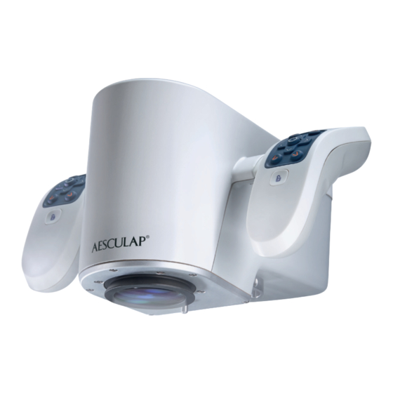
- Page 1 AESCULAP ® Instructions for use/Technical description Aesculap Aeos – Digital Surgical Microscope Page 1 of 36...
- Page 2 Page 2 of 36...
-
Page 3: Table Of Contents
AESCULAP ® Aesculap Aeos – Digital Surgical Microscope Legend 2.6.10 Shutdown procedure 2.6.11 Putting out of operation 1 3D surgical screen 2.6.12 Changing footswitch batteries 2 Control screen Software 3 Robotic arm Home screen 4 Camera Setup 5 Base 3.2.1... - Page 4 Technical data Product description Classification acc. to Directive 93/42/EEC and Regulation (EU) The Aesculap Aeos is a freestanding, digital surgical microscope in a look- 2017/745 over configuration. The Aesculap Aeos does not utilize traditional micro- Performance data, information about standards...
-
Page 5: Camera
Handle buttons (default setting) The EPU is powered off / power failure. The Aesculap Aeos is designed to be controlled primarily through the but- The system is powered off. tons on the handles of the sides of the camera. The default layout of the handles is shown below. - Page 6 IEC/DIN EN 60601-1 requirements for ME-systems. Any individ- The UPS is able to buffer the Aesculap Aeos system for at least 5 seconds ual connecting devices with one another is responsible for such in the case of an external power interruption.
-
Page 7: Display (Optional)
Connection an optional display can be the primary display. Blinking No radio connection, e.g. radio range error The following display stands are approved for use with the Aesculap Aeos: green or receiver not online Art. no. Designation Blinking Warning: possible loss of connectivity Pairing mode active for ≈... -
Page 8: Keyboard
FS097 Great Britain and Ireland Software module DUV 400 PV022 FS098 Mains cord black Japan, USA, Canada The DUV 400 is an accessory for the Aesculap Aeos and is used for viewing angled fluorescence of fluorophores, comprising: ■ GK537 Equipotential... -
Page 9: Safety Information
Minimize exposure to eyes and skin. ► Use appropriate shielding. 2.3.2 Product ► Make sure that no light from the Aesculap Aeos enters the patient’s Product-specific safety information eyes. Risk of fatal injury from electric shock! Fluorescent surgery ► Do not open the product. -
Page 10: Sterility
► Always carry and lift the footswitch using the carrying handle. Art. no. Designation ► Place footswitch on hanger at the base of the Aesculap Aeos when not in use. PV012SU Aesculap Aeos sterile drape ► Switch off Aesculap Aeos before cleaning or maintenance work on the The product is the only sterile component of the system. -
Page 11: 3D Display And Robotic Arm Workspace
3D display and robotic arm workspace Neurosurgery operating room layout (example) To help with positioning the Aesculap Aeos in the operating room, the base dimensions, the minimum and maximum extensions of the 3D dis- play arm, and the height and maximum extension of the robotic arm are shown below. -
Page 12: Connecting The Power Supply
► Lay the power cable in areas with minimal foot traffic. ► Place power cable on hanger at the base of the Aesculap Aeos when not in use. Functional test Fig. 10 Before turning the Aesculap Aeos system on Legend ►... -
Page 13: Turning The System On
Wait for the system to initialize (about 90 seconds). ► Under “Coupler”, press the “Reconfigure Coupler” button. The system will be ready for use once the Aesculap Aeos software has ► Press and hold the “Hold or Reconfigure position” button until the arm opened and the notification “Aesculap Aeos initializing, please wait…”... - Page 14 Notice the correct position of the drape lens, see Fig. 17. Fig. 14 ► Press the “Hold for Drape position” button in the Aesculap Aeos soft- ware until the movement is finished. Moving the robotic arm out of storage position and draping the Fig. 18...
-
Page 15: Starting A Case
If settings have been changed during the case, a message window will Note appear with options to discard changes, overwrite current profile or It is recommended to rebalance the Aesculap Aeos after draping, see create a new surgeon profile. Chapter 3.2.2. -
Page 16: Removing The Drape
To copy case media to an available local or externally connected drive, Note select the drive letter from the drop-down list, then press “Yes” The safe and all-pole disconnection of the Aesculap Aeos system from the – or – supply mains is only guaranteed when the power supply cord is unplugged. -
Page 17: 2.6.12 Changing Footswitch Batteries
■ Rebalance the Aesculap Aeos ■ Software Enter recovery state ■ Reconfigure the coupler. Home screen The Aesculap Aeos software starts on the home screen on the control screen. Fig. 30 Fig. 31 Symbols Soft stop 3.2.1 Preset positions As a risk control, the software has a soft stop button in the... -
Page 18: Rebalance Scope
Rebalance scope Moving the robotic arm to its limits can affect the Aesculap Aeos’ bal- ance. To correct the presence of any drift, the Aesculap Aeos can be rebal- anced. The Aesculap Aeos robotic arm is factory-calibrated. It is recommended to... -
Page 19: Control Panel
Fig. 35 ality of the integrated fluorescence module. Legend ► Ensure that the Aesculap Aeos system is in a dark room, with no other 1 “Camera” tab illumination other than the Aesculap Aeos integrated lighting and the 2 “Robot” tab system displays. -
Page 20: Robot
Optimum illumination in DIR 800 fluorescence module is achieved if the illuminated field of focus diameter on the Aesculap Aeos is set to the middle position of the live image, i.e. a small depth of field is set, as well as the smallest acceptable working distance. -
Page 21: Setup
► The “Lock On Target” function locks the Aesculap Aeos onto a selected To set a new waypoint, press the corresponding button on the handles focal target in the live image. When enabled, directional movement will / foot switch or the corresponding function in the Quick Access Bar rotate around the focal target instead of moving linearly. -
Page 22: Image Modes
If “Focus Indicator” is enabled the focus indicator will appear when man- ual focus or auto focus is performed. It will also appear when Aesculap Aeos is moved via any method. The focus indicator disappears when movement and focussing are completed. -
Page 23: Digital Aperture
Select “White Balance” to perform white balance and follow the on- screen instructions to complete the white balance process. ► Test the colors by viewing your hand under the Aesculap Aeos. Repeat the process if the colors look incorrect. 3.6.6 Recording Fig. 45... -
Page 24: Display
If unchecked, the software will only polarity, resolution, and view type) will automatically appear on the live record the raw Aesculap Aeos input (default: unchecked). image of each connected monitor while the Display settings panel is open. -
Page 25: Input Source
Note ► When “Detect” is set to “Off”, press the “3D Format” drop-down list to The DICOM module requires a license for use with the Aesculap Aeos sys- change the 3D format for the selected display from the following tem. -
Page 26: 3.6.11 Footswitch
In the Footswitch panel the footswitch can be paired with the Aesculap Aeos and the layout and function of the footswitch can be con- Show Button Layout Toggles showing the button layout of the han- figured. -
Page 27: 3.6.12 About
In this mode all indica- tion LEDs are turned off. Enabling the footswitch After every restart of the Aesculap Aeos software, the footswitch must be enabled, see Chapter 2.6.3. Available footswitch button functions The same button functions as for the handle are also available for the footswitch, see Chapter 3.6.10... -
Page 28: Robotic Arm State Indicators
Displayed when moving the arm Note with Restrictions with the handles and arm reaches a The Aesculap Aeos application does not need to be closed in order to view directional limit the user manual. Uncalibrated State Displayed when arm hasn’t been... -
Page 29: Robot Malfunction
Then restart the system. If issues remain, contact Aesculap Technical Ser- vice, see Chapter 7.2 Control screen not Use keyboard to shut down and reboot the working Aesculap Aeos. Keyboard not work- Disconnect and reconnect USB plug. Page 29 of 36... -
Page 30: Error Messages In The Software
Image errors during Observe “Notes on electromagnetic compatibility Already initialized Restart the system. high frequency sur- (EMC) for the Aesculap Aeos (Digital Surgical If that does not help, contact the Aesculap Aeos Head Manager gical applications Microscope) PV010” TA015615-EMV local Aesculap representative or... -
Page 31: Reprocessing Procedure
50%. Turn the system off and allow it to cool when safe. For the Aesculap Aeos there is no set maximum number of uses and reprocessing cycles. Connect Aesculap Aeos The system is not connected to the camera. -
Page 32: Wipe Disinfection
The Aesculap Aeos system will not allow the user to make new record- ings if the storage drive is filled up. -
Page 33: Security
Aesculap Aeos does not support any specific security measures. DANGER It is assumed that Aesculap Aeos is used within a secured environment. It Danger to life of patients and users if the product malfunctions is assumed that a secured environment includes at a minimum: and/or protective measures fail or are not used! ■... -
Page 34: Technical Data
Main power switch. Art. no. Designation Class Press to turn the system ON. Press again to turn the system OFF PV010 Aesculap Aeos (Digital Surgical Microscope) Base Fuse Performance data, information about standards Product label AC input Weight (basic hardware 300 kg / 661 lbs. -
Page 35: Distributor In The Us/Contact In Canada For Product Information And Complaints
Symbol Location Description Symbol Location Description Control USB 3.0 port Packaging Keep dry screen mount label Packaging This side up Base inter- USB 2.0 port face Base inter- DisplayPort Packaging Fragile, handle with care face Base inter- HDMI port Packaging Do not stack face Base inter-... - Page 36 Aesculap AG | Am Aesculap-Platz | 78532 Tuttlingen | Germany Phone +49 (0) 7461 95-0 | Fax +49 (0) 7461 95-26 00 | www.bbraun.com ® AESCULAP – a B. Braun brand SOP-AIC-5001887 (TA015615) 2022-09 Rev. 5 Page 36 of 36...
Need help?
Do you have a question about the Aesculap Aeos and is the answer not in the manual?
Questions and answers