
Related Manuals for Microchip Technology EV20F92A


Summary of Contents for Microchip Technology EV20F92A
- Page 1 EV20F92A Serial Memory SPI Evaluation Kit User’s Guide 2022 Microchip Technology Inc. and its subsidiaries DS20006685A...
- Page 2 Microchip Technology Inc. in other countries. stated. GestIC is a registered trademark of Microchip Technology Germany II GmbH & Co. KG, a subsidiary of Microchip Technology Inc., in other countries. All other trademarks mentioned herein are property of their respective companies.
-
Page 3: Table Of Contents
Table of Contents Preface ........................... 5 Chapter 1. Product Overview 1.1 Introduction ..................... 9 1.2 EV20F92A Evaluation Kit Overview ............... 9 1.3 Evaluation Kit Contents .................. 9 1.4 Operational Requirements ................10 Chapter 2. Installation and Operation 2.1 Introduction ....................11 2.2 Installing the Graphical User Interface (GUI) .......... - Page 4 EV20F92A Serial Memory SPI Evaluation Kit User’s Guide A.3 USB Base Board (02-10682) ............... 42 Appendix B. Bill of Materials (BOM) Worldwide Sales and Service ..................46 2022 Microchip Technology Inc. and its subsidiaries DS20006685A-page 4...
-
Page 5: Preface
• Customer Support • Revision History DOCUMENT LAYOUT This document describes how to use the EV20F92A Serial Memory SPI Evaluation Kit as a tool to demonstrate the best-in-class features, functionality and low-power operation of Microchip’s SPI Serial EEPROM devices. The document is organized as follows: •... - Page 6 EV20F92A Serial Memory SPI Evaluation Kit User’s Guide CONVENTIONS USED IN THIS GUIDE This manual uses the following documentation conventions: DOCUMENTATION CONVENTIONS Description Represents Examples Arial font: ® Italic characters Referenced books MPLAB X IDE User’s Guide Emphasized text ...is the only compiler...
- Page 7 EV20F92A Serial Memory SPI Evaluation Kit User’s Guide RECOMMENDED READING This user’s guide describes how to use the EV20F92A Serial Memory SPI Evaluation Kit. The following documents are available and recommended as supplemental reference resources. • Serial Memory SPI Quick Start Guide – “Serial Memory SPI Evaluation Kit Quick Start Guide”...
- Page 8 EV20F92A Serial Memory SPI Evaluation Kit User’s Guide ® • MPLAB IDE – The latest information on Microchip MPLAB X IDE, the Windows Integrated Development Environment for development systems tools. This list is focused on the MPLAB X IDE, MPLAB X IDE Project Manager, MPLAB Editor and MPLAB SIM simulator, as well as general editing and debugging features.
-
Page 9: Chapter 1. Product Overview
Microchip Technology’s EV20F92A Serial Memory SPI Evaluation Kit allows the user to read, write and verify Microchip’s Serial EEPROM devices using the SPI bus protocol. This chapter introduces the EV20F92A Serial Memory SPI Evaluation Kit and provides an overview of its features. Topics covered include: • EV20F92A Evaluation Kit Overview •... -
Page 10: Operational Requirements
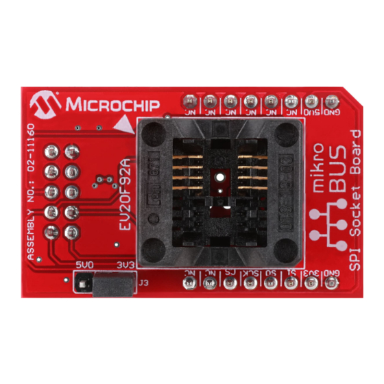
EV20F92A Serial Memory SPI Evaluation Kit User’s Guide FIGURE 1-2: USB BASE BOARD (02-10682) The SPI Socket Board also includes mikroBUS™ headers that allow the user to further develop applications by using the Socket Board with Microchip's extensive Develop- ment Tool offering. The V for the mikroBUS™... -
Page 11: Chapter 2. Installation And Operation
The following steps are needed to successfully install the GUI software: Note: If an earlier version of the EV20F92A SPI Evaluation Kit GUI was previously installed, it is recommended to uninstall the previous version before install- ing the new version. This will ensure robust GUI operation. - Page 12 EV20F92A Serial Memory SPI Evaluation Kit User’s Guide FIGURE 2-1: GUI INSTALLATION LOCATION 6. The next step is to select the Start Menu folder. By default, the setup will create a Start Menu folder named Microchip (if one is not already present on the user’s PC).
-
Page 13: Microsoft Windows Desktop Runtime
GUI READY TO INSTALL MICROSOFT WINDOWS DESKTOP RUNTIME The Microchip Technology Serial Memory SPI Evaluation Kit requires that .NET 5.0 or higher is installed on the user's PC for running WPF applications. Follow the on-screen instructions and complete the .NET installation. Once complete, the installation will then install the FLIP software.:... -
Page 14: Flexible In-System Programming (Flip) Software
EV20F92A Serial Memory SPI Evaluation Kit User’s Guide FLEXIBLE IN-SYSTEM PROGRAMMING (FLIP) SOFTWARE The Microchip Technology Serial Memory Evaluation Kits have a built-in ability to update the USB Base Board using a sequence of steps, along with using the Atmel FLexible In-system Programming (FLIP) software. - Page 15 EV20F92A Serial Memory SPI Evaluation Kit User’s Guide FIGURE 2-5: JAVA RUNTIME TYPICAL SETUP Typical Setup option Accept button 3. Let the program setup the Java Runtime. A progress or status bar is included to show the overall progress of the installation. Once completed, press the Finish button to complete the Java Runtime installation.
- Page 16 EV20F92A Serial Memory SPI Evaluation Kit User’s Guide FIGURE 2-7: FLIP SETUP WIZARD 5. Read the License Agreement. When finished, accept the terms in the License Agreement by checking the box and press the Next button to continue. FIGURE 2-8: FLIP LICENSE AGREEMENT “I accept”...
- Page 17 EV20F92A Serial Memory SPI Evaluation Kit User’s Guide FIGURE 2-9: FLIP INSTALLATION LOCATION 7. Choose a Start Menu folder. By default, the Start Menu folder is set to Flip 3.4.7, where 3.4.7 indicates the FLIP version. It is recommended that the default Start Menu folder is used.
- Page 18 EV20F92A Serial Memory SPI Evaluation Kit User’s Guide FIGURE 2-11: FLIP SOFTWARE UTILITY COMPLETE 9. Let the program setup the SPI GUI. A progress or status bar is included to show the overall progress of the installation. Once completed, press the Finish button...
-
Page 19: Evaluation Kit Setup Procedure
Board into one of their computer’s USB ports. Once the USB Base Board enumerates on the user’s PC, open the GUI by selecting either the desktop icon (SPI GUI) or nav- igating to the Start Menu folder that was created when the EV20F92A SPI Evaluation Kit GUI software was installed. -
Page 20: Chapter 3. Graphical User Interface (Gui)
If the GUI version is earlier than the USB Base Board, download the latest version of the GUI (refer to Section 2.2 “Installing the Graphical User Interface (GUI)” for additional information). FIGURE 3-1: GRAPHICAL USER INTERFACE 2022 Microchip Technology Inc. and its subsidiaries DS20006685A-page 20... -
Page 21: Main Title Bar
EV20F92A Serial Memory SPI Evaluation Kit User’s Guide MAIN TITLE BAR The title bar displays the GUI version and the USB Base Board connection status. Figure 3-2, shown below, illustrates a GUI version of 1.0.0.0. FIGURE 3-2: TITLE BAR QUERY DEVICE The GUI will perform an auto-query when the GUI is launched or when the USB Base Board is initially connected to the PC. -
Page 22: Device Conditions
EV20F92A Serial Memory SPI Evaluation Kit User’s Guide 3.4.1 Evaluation Kit Part Number This displays the evaluation kit part number, EV20F92A. 3.4.2 Firmware Version This is the version of the firmware programmed in the USB Base Board. 3.4.3 Evaluation Kit Protocol Identifies the communication protocol used by the evaluation kit’s socket board. -
Page 23: Device Specification
EV20F92A Serial Memory SPI Evaluation Kit User’s Guide DEVICE SPECIFICATION The Device Specification pane (Figure 3-7) displays key device parameters that can be found in the installed device’s data sheet. FIGURE 3-7: DEVICE SPECIFICATION PANE SET HARDWARE FEATURES The Set Hardware Features pane... -
Page 24: Gui Memory Array
EV20F92A Serial Memory SPI Evaluation Kit User’s Guide GUI MEMORY ARRAY The GUI memory array is initially populated with the data read from the installed Serial EEPROM. The data of the GUI memory array is organized in 8-byte rows, left to right and in ascending order. -
Page 25: Array Buttons
EV20F92A Serial Memory SPI Evaluation Kit User’s Guide 3.10 ARRAY BUTTONS The array buttons, which are located below the GUI Security register, allow the user to perform read and write operations to the Serial EEPROM, navigate to specific word addresses in the GUI memory array and also provides various support functions. - Page 26 EV20F92A Serial Memory SPI Evaluation Kit User’s Guide 3.10.3 Program The Program feature can be used to write the GUI array buffer to the installed Serial EEPROM memory array. When the Program button is pressed, the current internal GUI buffer will be written to the Serial EEPROM memory. The Program feature must be used when a cell is updated (green font), or when a file (.hex or .txt) is loaded.
- Page 27 EV20F92A Serial Memory SPI Evaluation Kit User’s Guide FIGURE 3-14: READ OPERATION Read button Close button 3.10.5 Write The Write feature allows the user to write the entire Serial EEPROM memory array, a specific word address or a range of word addresses. When the Write button is pressed, a pop-up window appears, allowing the user to enter details related to the write opera- tion to be performed.
- Page 28 EV20F92A Serial Memory SPI Evaluation Kit User’s Guide FIGURE 3-16: WRITE OPERATION Clear Array button Generate Pattern button Close button Write button 3.10.6 Save The Save button gives the user the ability to save the current state of the internal GUI buffer.
-
Page 29: Status Register
EV20F92A Serial Memory SPI Evaluation Kit User’s Guide 3.11 STATUS REGISTER The Status Register tab gives the user access to the STATUS register for the con- nected Serial EEPROM. The tab gives a breakdown of each writable bit or latch value. -
Page 30: Enhanced Write Protection
EV20F92A Serial Memory SPI Evaluation Kit User’s Guide 3.12 ENHANCED WRITE PROTECTION The Enhanced Write Protection tab gives the user access to the various Memory Par- tition Registers (MPRs) for the connected Serial EEPROM. The tab allows the user to select each partition behavior and end point address. -
Page 31: Security Register
EV20F92A Serial Memory SPI Evaluation Kit User’s Guide 3.13 SECURITY REGISTER The Security register consists of two regions (size based on the selected supported device) with a factory-programmed unique serial number in the lower 16 bytes (address 00h to 0Fh) in the first section and a user-programmable lockable identification page in the second section. - Page 32 EV20F92A Serial Memory SPI Evaluation Kit User’s Guide FIGURE 3-20: FIGURE 3-18: READ SECURITY REGISTER 3.13.3 Write The Write feature allows the user to write data to the lockable ID page. The default Address is byte0 of the lockable ID page, but can be changed by the user.
-
Page 33: Transaction Log
EV20F92A Serial Memory SPI Evaluation Kit User’s Guide FIGURE 3-22: LOCK SECURITY REGISTER 3.14 TRANSACTION LOG The Transaction Log records all SPI communication with the installed device as well as highlights the communication protocol according to the legend. The Transaction Log reports the data on the SPI bus in hexadecimal. -
Page 34: Chapter 4. Usb Base Board Firmware Update
Chapter 4. USB Base Board Firmware Update INTRODUCTION The Microchip Technology Serial Memory Evaluation kit has a built-in ability to update the USB Base Board using a sequence of steps outlined by GUI or using the Atmel FLexible In-system Programming (FLIP) software. - Page 35 EV20F92A Serial Memory SPI Evaluation Kit User’s Guide FIGURE 4-2: USB BASE BOARD BUTTONS HWB button RESET button Once the HWB and RESET buttons have been located, use the specific press and hold sequence shown below to enable DFU mode on the USB Base Board: •...
-
Page 36: Flip Software Utility
EV20F92A Serial Memory SPI Evaluation Kit User’s Guide FLIP SOFTWARE UTILITY Once the USB Base Board has DFU mode enabled and the COM port is relearned by the PC, perform the following sequence using the FLIP Software Utility to update the USB Base Board firmware: 1. - Page 37 EV20F92A Serial Memory SPI Evaluation Kit User’s Guide 3. Once the target device has been selected, click on the Communication Medium icon as shown below and select “USB”. Once “USB” is selected, an additional dialog box is displayed. Press the Open button to continue.
- Page 38 C:\Program Files (x86)\Microchip\Serial Memory Evaluation Kits\SPI\Firmware Note: If the default installation was not used when the EV20F92A SPI GUI was installed, it is the user’s responsibility to determine the SPI firmware file location. 6. Once the HEX file has been loaded into the FLIP Software Utility, press the Run...
-
Page 39: Chapter 5. Troubleshooting Guide
SPI Socket Board into the USB Base Board and restart the GUI. If the problem persists, contact your local Sales representative for additional support or create a support ticket at www.microchip.com/support. 2022 Microchip Technology Inc. and its subsidiaries DS20006685A-page 39... -
Page 40: Appendix A. Schematics
EV20F92A SERIAL MEMORY SPI EVALUATION KIT USER’S GUIDE Appendix A. Schematics INTRODUCTION This appendix contains the following schematics for the EV20F92A Serial Memory SPI Evaluation Kit: • SPI Socket Board (04-11160) • USB Base Board (02-10682) Note: Electronic versions of the SPI Socket Board and USB Base Board sche- matics can be downloaded from http://www.microchip.com/EV20F92A... -
Page 41: Spi Socket Board (04-11160)
SPI SOCKET BOARD (04-11160) ECO# DESCRIPTION DATE Added MikroE Headers 12/07/2020 DUT Socket Circuit Board Header MikroE Headers 0.1uF 470k Temperature Sensor Circuit OTS-8(16)-1.27-03 0.1uF ALERT 652C0082211W AT30TSE752A Board Serialization Circuit 0.1uF Drawn By: Erik Fasnacht AT24CS02-SSHM-T Engineer: Erik Fasnacht PartNumber: Project Title EV90F92A... - Page 42 USB BASE BOARD (02-10682) R E V IS IO N R E C O R D E C O N O : A PPR O V E D: DA TE : V C C F D3 F D4 F D1 F D2 X TA L1 F IDU C IA L_ PA D...
- Page 43 X5R 0402 C101, C102 Note 1: The components listed in this Bill of Materials are representative of the PCB assembly. The released BOM used in manufacturing uses all RoHS-compliant components. 2022 Microchip Technology Inc. and its subsidiaries DS20006685A-page 43...
- Page 44 EV20F92A Serial Memory SPI Evaluation Kit User’s Guide TABLE B-2: USB BASE BOARD (02-10682) (CONTINUED) Reference Description Manufacturer Part Number C11, C12, C13, Ceramic capacitor, 4.7 µF, 10V C14, C17, C19, KEMET C0603C475K8PACTU X5R 0603 C20, C21 Ceramic capacitor, 10 µF, 6.3V C103 Taiyo Yuden Co., Ltd.
- Page 45 EV20F92A Serial Memory SPI Evaluation Kit User’s Guide TABLE B-2: USB BASE BOARD (02-10682) (CONTINUED) Reference Description Manufacturer Part Number IC DAC 12BIT SNGL W/SPI MCP4921T-E/MS Microchip Technology Inc. 8-MSOP Boost regulator adjustable IC Microchip Technology Inc. MCP16251T-I/CH 0.65A SYNC SOT23 IC OPAMP GP 3 MHz RRO Analog Devices, Inc.
- Page 46 Tel: 46-31-704-60-40 Tel: 631-435-6000 Sweden - Stockholm San Jose, CA Tel: 46-8-5090-4654 Tel: 408-735-9110 UK - Wokingham Tel: 408-436-4270 Tel: 44-118-921-5800 Canada - Toronto Fax: 44-118-921-5820 Tel: 905-695-1980 Fax: 905-695-2078 2022 Microchip Technology Inc. and its subsidiaries DS20006685A-page 46 09/14/21...
Need help?
Do you have a question about the EV20F92A and is the answer not in the manual?
Questions and answers