
Related Manuals for Microchip Technology EVB-LAN9252-HBI+


Summary of Contents for Microchip Technology EVB-LAN9252-HBI+
-
Page 1: Evaluation Board
EVB-LAN9252-HBI+ ® EtherCAT Evaluation Board User’s Guide 2015-2016 Microchip Technology Inc. DS50002333C... - Page 2 SQTP is a service mark of Microchip Technology Incorporated in the U.S.A. Silicon Storage Technology is a registered trademark of Microchip Technology Inc. in other countries. GestIC is a registered trademarks of Microchip Technology Germany II GmbH & Co. KG, a subsidiary of Microchip Technology Inc., in other countries.
- Page 3 Object of Declaration: EVB-LAN9252-HBI+ 2015-2016 Microchip Technology Inc. DS50002333C-page 3...
- Page 4 EVB-LAN9252-HBI+ EtherCAT® Evaluation Board User’s Guide NOTES: 2015-2016 Microchip Technology Inc. DS50002333C-page 4...
-
Page 5: Table Of Contents
2.6.1 Potentiometer .................... 27 2.6.2 Temperature Sensor ................. 27 2.6.3 UART RS-232 ................... 27 2.6.4 DAC ......................27 2.7 Limitations ....................27 2.8 Mechanicals ....................28 Chapter 3. Software Development Kit 3.1 Prerequisites ....................29 2015-2016 Microchip Technology Inc. DS50002333C-page 5... - Page 6 Appendix A. Evaluation Board Photo A.1 Introduction ....................37 Appendix B. Evaluation Board Schematics B.1 Introduction ....................38 Appendix C. Bill of Materials (BOM) C.1 Introduction ....................49 Worldwide Sales and Service ..................54 2015-2016 Microchip Technology Inc. DS50002333C-page 6...
-
Page 7: Preface
– This appendix shows the EVB-LAN9252-HBI+. • Appendix B. “Evaluation Board Schematics” – This appendix shows the EVB-LAN9252-HBI+ schematics. • Appendix C. “Bill of Materials (BOM)” – This appendix includes the EVB-LAN9252-HBI+ Bill of Materials (BOM). 2015-2016 Microchip Technology Inc. DS50002333C-page 7... -
Page 8: Conventions Used In This Guide
Curly brackets and pipe Choice of mutually exclusive errorlevel {0|1} character: { | } arguments; an OR selection Ellipses... Replaces repeated text var_name [, var_name...] Represents code supplied by void main (void) user { ... 2015-2016 Microchip Technology Inc. DS50002333C-page 8... -
Page 9: The Microchip Web Site
PICSTART Plus and PIC-kit 2 and 3. CUSTOMER SUPPORT Users of Microchip products can receive assistance through several channels: • Distributor or Representative • Local Sales Office • Field Application Engineer (FAE) • Technical Support 2015-2016 Microchip Technology Inc. DS50002333C-page 9... -
Page 10: Document Revision History
Section 2.4.4 “DIGIO/HBI/ Added additional information on DIGIO mode. SPI+GPIO Selection” Table 2-13, Table 2-14, Simplified table and added note under each table for clarity. and Table 2-15 DS50002333A (02-27-15) Initial Release of Document 2015-2016 Microchip Technology Inc. DS50002333C-page 10... -
Page 11: Chapter 1. Overview
HBI/SPI+GPIO Interface and corresponding jumper configurations. The LAN9252 is connected to an RJ45 Ethernet jack with integrated magnetics for 100BASE-TX connectivity. A simplified block diagram of the EVB-LAN9252-HBI+ is shown in Figure 1-1. 2015-2016 Microchip Technology Inc. DS50002333C-page 11... - Page 12 AARDVARK Selection HBI or SPI+GPIO Selection EEPROM Microchip LAN9252 Straps Crystal Port 0 Port 1 100BASE-TX 100BASE-TX Fiber- Fiber- Ethernet Ethernet Magnetics & Magnetics & Port 0 Port 1 RJ45 RJ45 Ethernet Ethernet 2015-2016 Microchip Technology Inc. DS50002333C-page 12...
-
Page 13: References
IDE - Integrated Development Environment ESC - EtherCAT® Slave Controller EVB - Engineering Validation Board HAL - Hardware Abstraction Layer HBI - Host Bus Interface SPI - Serial Protocol Interface SSC - Slave Stack Code 2015-2016 Microchip Technology Inc. DS50002333C-page 13... -
Page 14: Chapter 2. Board Details & Configuration
GPIO pin [95(RG14)]. The SW10 switch is used for this selection, as shown in Table 2-1. TABLE 2-1: RESET CONFIGURATION SWITCH Switch Short Pins Knob Position Function SW10 System Reset (SYS_RESETN) (Default) SW10 GPIO Reset (RST_GPIO) 2015-2016 Microchip Technology Inc. DS50002333C-page 14... -
Page 15: Clock
The following sub-sections describe the various board features and configuration set- tings. A top view of the EVB-LAN9252-HBI+ is shown in Figure 2-1. Figure 2-2 details new features. FIGURE 2-1: EVB-LAN9252-HBI+ TOP VIEW WITH CALLOUTS 2015-2016 Microchip Technology Inc. DS50002333C-page 15... -
Page 16: Strap Options
The LAN9252 supports 100BASE-TX (Copper) and 100BASE-FX (Fiber) modes. In 100BASE-FX operation, the presence of the receive signal is indicated by the external transceiver as either an open-drain, CMOS level, Loss of Signal (SFP) or a LVPECL Signal Detect (SFF). 2015-2016 Microchip Technology Inc. DS50002333C-page 16... - Page 17 Additionally, the signal routing resistors detailed in Table 2-7 must be assembled for Fiber Mode operation. TABLE 2-7: FIBER MODE SIGNAL ROUTING RESISTORS Resistors Description R16, R18, R20, R22 Port 0 Fiber Mode enabled R30, R32, R34, R36 Port 1 Fiber mode enabled 2015-2016 Microchip Technology Inc. DS50002333C-page 17...
-
Page 18: Led Indicators
Flickering (on 50ms, off 50ms) The device is booting and has not yet entered the INITIALIZATION state, or the device is in the BOOTSTRAP state and firmware download is in progress. (Optional. Off when not implemented.) 2015-2016 Microchip Technology Inc. DS50002333C-page 18... -
Page 19: Eeprom Switch
An appropriate PDI configuration must be set in the ESC configuration area of the EEPROM. TABLE 2-12: HBI/SPI+GPIO SWITCH CONFIGURATIONS Switch Description Settings SW11 to SW21 DIGIO/HBI Mode (Default) SW11 to SW21 Down SPI+GPIO Mode 2015-2016 Microchip Technology Inc. DS50002333C-page 19... - Page 20 Table 2-13 details the switch selection for Multiplexed Mode. TABLE 2-13: MULTIPLEXED HBI MODE SELECTION Switch Switch Knob Position Start Destination Down A0_AD15 A0_CONFIG3 RD_RDWR GPMC_DIR Down ALELO_A1 A1_CONFIG3 Down WR_ENB GPMC_DE0N_CLE Down ALEHI_A2 A2_CONFIG3 SW24 A0_CONFIG3 GPMC_A0_ALE SW25 A1_CONFIG3 GPMC_A1_ALEHI 2015-2016 Microchip Technology Inc. DS50002333C-page 20...
- Page 21 When the switch knob is in the up position, pins 1-3 are shorted and no dot can be seen. 16-Bit Indexed Mode Figure 2-7 details the switch selection for 16-Bit Indexed Mode. FIGURE 2-7: 16-BIT INDEXED HBI MODE SELECTION 2015-2016 Microchip Technology Inc. DS50002333C-page 21...
- Page 22 J11 and J12 are used as Aardvark/SPI/SQI headers. The respective pin details are shown in Table 2-17. TABLE 2-17: J11 & J12 HEADER PINOUT Signal Pin Number J11.1 J11.3 J11.7 SCS# J11.9 SI(SIO0) J11.8 SO(SIO1) J11.5 SIO2 J12.3 SIO3 J12.4 2015-2016 Microchip Technology Inc. DS50002333C-page 22...
-
Page 23: Soc
Whenever an add-on board/SoC is used, the switch knob must be in the up position. TABLE 2-19: SOC SELECTION Switch Position Settings SW26 Down On-board PIC enabled SW26 Add-on board/SoC enabled 2015-2016 Microchip Technology Inc. DS50002333C-page 23... - Page 24 ID Selection PIC Pin 10k to Pull Pins to Short Signal Name Signal Number High for Pull Low ID0_SELECT_RB0 R123 32:31 ID_SELECT_RB1 R124 30:29 ID_SELECT_RB2 R125 28:27 ID_SELECT_RB3 R126 26:25 ID_SELECT_RB4 R127 24:23 2015-2016 Microchip Technology Inc. DS50002333C-page 24...
-
Page 25: Digio & Spi+16Gpio Signals On P1 And P2 Headers
OE_EXT P1.7 A0/D15 AD15 DIGIO9 P1.15 AD14 DIGIO8 P1.16 AD13 DIGIO7 P1.11 AD12 DIGIO6 P1.12 AD11 DIGIO5 P1.17 AD10 DIGIO4 P1.14 LATCH_IN P1.13 DIGIO2 P1.19 DIGIO1 P1.4 DIGIO0 P1.3 OUTVALID P1.22 DIGIO3 P1.23 2015-2016 Microchip Technology Inc. DS50002333C-page 25... -
Page 26: Spi+Gpio On P1 And P2 Headers (Up To 16 Bits Supported)
GPI8/GPO8 P1.16 AD13 GPI7/GPO7 P1.11 AD12 GPI6/GPO6 P1.12 AD11 GPI5/GPO5 P1.17 AD10 GPI4/GPO4 P1.14 P1.13 GPI2/GPO2 P1.19 GPI1/GPO1 P1.4 GPI0/GPO0 P1.3 SCS# P1.22 GPI3/GPO3 P1.23 SIO3 P1.6 SIO2 P1.5 SO/SIO1 P1.24 SI/SIO0 P1.25 2015-2016 Microchip Technology Inc. DS50002333C-page 26... -
Page 27: Additional Features
The EVB-LAN9252-HBI+ has the following limitations: 1. While the LAN9252 supports both SFP and SFF Fiber Modes, the EVB-LAN9252-HBI+ supports only the SFP Fiber Mode. 2. SQI is not supported when using the on-board PIC32MX. 2015-2016 Microchip Technology Inc. DS50002333C-page 27... -
Page 28: Mechanicals
EVB-LAN9252-HBI+ EtherCAT® Evaluation Board User’s Guide MECHANICALS FIGURE 2-10: EVB-LAN9252-HBI+ MECHANICAL DIMENSIONS 2015-2016 Microchip Technology Inc. DS50002333C-page 28... -
Page 29: Chapter 3. Software Development Kit
This software project has been tested with the EVB-LAN9252-HBI+ using the PIC32MX SoC. Figure 3-1 provides an architectural block diagram of the SDK’s various source mod- ules. The subsequent sections detail these blocks. 2015-2016 Microchip Technology Inc. DS50002333C-page 29... -
Page 30: User Module
This code block contains the low level layer that provides software hooks/APIs to the application module and slave stack, allowing communication between these modules and the hardware resources. For additional information, refer to the ReadMe.txt file located in the project source folder. 2015-2016 Microchip Technology Inc. DS50002333C-page 30... -
Page 31: Using The Sample Project
2. Open the MPLAB IDE and import the SSC project into the IDE. FIGURE 3-2: MPLAB IDE OPEN PROJECT FIGURE 3-3: MPLAB IDE PROJECT DIRECTORY The target directory contains two project folders: • PIC32-HBI Project Folder • PIC32 Project Folder 2015-2016 Microchip Technology Inc. DS50002333C-page 31... - Page 32 SoC. • Refer to the LAN9252 data sheet for more details on these HBI interface and its modes. • Refer to Section 2.4.4 “DIGIO/HBI/SPI+GPIO Selection” for SPI jumper configura- tions. 2015-2016 Microchip Technology Inc. DS50002333C-page 32...
-
Page 33: Compiling And Programming Soc Firmware
EVB’s JTAG pins. (This demo project is debugged with the PICkit-3 In-Circuit debugger/programmer). 4. To program the PIC32 SoC, click the “Make and Program Device Main Project” button. FIGURE 3-7: MPLAB IDE PROGRAM DEVICE 2015-2016 Microchip Technology Inc. DS50002333C-page 33... -
Page 34: Programming The Lan9252 Eeprom
2. If TwinCAT installed successfully, a TwinCAT icon will be shown in the bot- tom-right corner of the desktop. After clicking the icon, a pop-up list will display. Select “TwinCAT XAE (VS 2013)”, as shown in Figure 3-9. FIGURE 3-9: TWINCAT SYSTEM MANAGER 2015-2016 Microchip Technology Inc. DS50002333C-page 34... - Page 35 4. Scan for EtherCAT® slave devices by expanding “I/O” and right clicking “Devices” and then selecting “Scan”, as shown in Figure 3-11. FIGURE 3-11: TWINCAT SCAN DEVICES 5. After scanning is complete, a window showing devices found will appear similar to Figure 3-12. 2015-2016 Microchip Technology Inc. DS50002333C-page 35...
- Page 36 LAN9252 listing and select “EEPROM Update” from the contextual menu. FIGURE 3-13: TWINCAT EEPROM UPDATE 8. Upon selecting “EEPROM Update”, the Write EEPROM window will open. Click the “OK” button to initiate EEPROM programming (Figure 3-14). FIGURE 3-14: TWINCAT WRITE EEPROM 2015-2016 Microchip Technology Inc. DS50002333C-page 36...
-
Page 37: Appendix A. Evaluation Board Photo
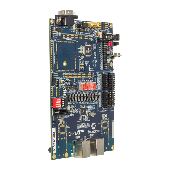
EVB-LAN9252-HBI+ ETHERCAT® EVALUATION BOARD USER’S GUIDE Appendix A. Evaluation Board Photo INTRODUCTION This appendix shows the EVB-LAN9252-HBI+ Evaluation Board. FIGURE A-1: EVB-LAN9252-HBI+ EVALUATION BOARD 2015-2016 Microchip Technology Inc. DS50002333C-page 37... -
Page 38: Appendix B. Evaluation Board Schematics
EVB-LAN9252-HBI+ ETHERCAT® EVALUATION BOARD USER’S GUIDE Appendix B. Evaluation Board Schematics INTRODUCTION This appendix shows the EVB-LAN9252-HBI+ Evaluation Board Schematics. 2015-2016 Microchip Technology Inc. DS50002333C-page 38... - Page 39 FIGURE B-1: EVB-LAN9252-HBI+ SCHEMATIC POWER SUPPLY & RESET POWER SUPPLY 3 V REGULATOR, 3A ORANGE ( 3V3 fixed when Rb=503e) BLACK BLACK 5V_EXT 5V_SW VOUT EN12_1 ENABLE TRIM 2A/0.05DCR Switch, SPDT, Slide 3_Amp 470R 4.7uF P/N:1101M2S3CQE2 3.30K 10uF 0.1uF OKR-T/3-W12-C 10uF 0.1uF (Ra)
- Page 40 FIGURE B-2: EVB-LAN9252-HBI+ SCHEMATIC LAN9252 Power Supply Filtering VDD33TXRX1 2A/0.05DCR VDDCR VDD12TX1 VDD12TX2 1.0uF 0.1uF VDD33TXRX2 2A/0.05DCR VDDCR 2A/0.05DCR 1.0uF 0.1uF BLM18EG221SN1D 2A/0.05DCR Note: OSCVSS need to connect to Chip gnd. 18pF 25.000MHz OSCVDD12 OSCI 25ppm FXSDA/FXLOSA OSCI FXSDENA/FXSDA/FXLOSA OSCO OSCO OSCVSS 18pF...
- Page 41 FIGURE B-3: EVB-LAN9252-HBI+ SCHEMATIC COPPER MODE INTERFACE VDD33TXRX1 Pulse J0011D01BNL 49.9R 49.9R 49.9R 49.9R 1/10W 1/10W 1/10W 1/10W RJ45 XMIT TXPA FX_SFP-TXPA COP-TXPA TXCT 4 & 5 TXNA FX_SFP-TXNA COP-TXNA LED1 (Green) = LINK/ACT LED2 (Yellow) = SPEED RXPA FX_SFP-RXPA COP-RXPA 7 &...
- Page 42 FIGURE B-4: EVB-LAN9252-HBI+ SCHEMATIC SFP INTERFACE Note:Place Note:Place capacitors, capacitors, Fiber Port 1 :SFP Interface Fiber Port 0 :SFP Interface and resistors and resistors close to FOT close to FOT 49.9R 49.9R 49.9R 49.9R 0.1uF 0.1uF FX_SFP-RXNA FX_SFP-RXNB 0.1uF FX_SFP-RXPA 0.1uF FX_SFP-RXPB FX_SFP-TXPA...
- Page 43 FIGURE B-5: EVB-LAN9252-HBI+ SCHEMATIC STRAP, GPIO, I2C & FXLOS GPIO [0:2] & LED_POL_Strap I2C EEPROM GPIO0 GPIO2 GPIO1 GPIO0 GPIO1 GPIO2 0.1uF LED0_ANODE LED1_ANODE LED2_ANODE LED0_CATHODE LED1_CATHODE I2C2_1 I2C2_SDA LED2_CATHODE I2C2_2 I2C2_3 I2C2_7 I2C2_SCL SW DIP-4/SM TH IC. 24FC04 Different sizes can be mounted I2C EEPROM Lower size Below 16K(2K X 8) GPIO0...
- Page 44 FIGURE B-6: EVB-LAN9252-HBI+ SCHEMATIC BOARD TO BOARD INTERFACE A4/DIGIO12/GPI12/GPO12/MII_RXD0 A3/DIGIO11/GPI11/GPO11/MII_RXDV ALEHI_A2 A2/ALEHI/DIGIO10/GPI10/GPO10/LINKACTLED2/MII_LINKPOL/LEDPOL6 ALELO_A1 Host SOC EEPROM A1/ALELO/OE_EXT/MII_CLK25 0.1uF RD_RDWR RD/RD_WR/DIGIO15/GPI15/GPO15/MII_RXD3 WR_ENB WR/ENB/DIGIO14/GPI14/GPO14/MII_RXD2 CS/DIGIO13/GPI13/GPO13/MII_RXD1 A0_AD15 A0/D15/AD15/DIGIO9/GPI9/GPO9/MII_RXER I2C3_1 I2C1_SDA AD14 D14/AD14/DIGIO8/GPI8/GPO8/MII_TXD3/TX_SHIFT1 I2C3_2 AD13 D13/AD13/DIGIO7/GPI7/GPO7/MII_TXD2/TX_SHIFT0 I2C3_3 AD12 D12/AD12/DIGIO6/GPI6/GPO6/MII_TXD1 I2C3_7 I2C1_SCL AD11 D11/AD11/DIGIO5/GPI5/GPO5/MII_TXD0 AD10 D10/AD10/DIGIO4/GPI4/GPO4/MII_TXEN SW DIP-4/SM AD9_SCK...
- Page 45 FIGURE B-7: EVB-LAN9252-HBI+ SCHEMATIC PIC32MX PWM1 & PWM2 Signal for Motor Control PWM2 HEADER 10x4 HEADER 10x4 HEADER 10x4 HEADER 10x4 WHITE WHITE J15A J15B J15C J15D *(1-2) Switch _IN RD15 RD11 PWM1 PWM2 RD14 LED_OUT *(1-2) 1-2* = External PWR External R140 HEADER 3X2...
- Page 46 FIGURE B-8: EVB-LAN9252-HBI+ SCHEMATIC GPIOS SW28 GPI0 GPIO0_CONFIG5 GPO0 JS102011CQN Digital INPUTS SW29 GPI1 GPIO1_CONFIG5 Input = one (Default); GPO1 Input = Zero (change the Switch position) JS102011CQN SW30 GPI2 GPIO2_CONFIG5 GPO2 JS102011CQN SW31 GPI3 GPIO3_CONFIG5 GPO3 JS102011CQN SW32 GPI4 SW34 Digital OUTUTS GPIO4_CONFIG5...
- Page 47 FIGURE B-9: EVB-LAN9252-HBI+ SCHEMATIC UART, ADC, &DAC POT (Analog Input) R146 POT1 3352T-1-103LF 1/10W SW50 R141 470R SW for Output ADC1 IN Switch _IN sw_pb_2P Default Short R145 LED_OUT LED for Input DAC (Analog output) Temp sensor R153 R154 1/10W 1/10W 10uF TEMP IN...
- Page 48 FIGURE B-10: EVB-LAN9252-HBI+ SCHEMATIC PIM R149 IRQ_PIM32MZ VDDCORE_PIM IRQ_PIM24 RD_RDWR_CONFIG3 WR_ENB_CONFIG3 PIM1 SoC_SOSCO AD5_CONFIG3 SoC_SOSCI SQI_D0 AD6_CONFIG3 AD7_CONFIG3 PIM_DIG_RC1 CS_CONFIG3 PIM_DIG_RC2 SQI_CS HEADER 14X2 PIM_DIG_RC3 PIM_DIG_RC4 IRQ_PIM24 PIM_DIG_RC1 PIM_PIN10 PIM_DIG_RC2 PIM_PIN11 PIM_DIG_RC3 PIM_PIN12 PIM CONN SoC_OSC2 PIM_DIG_RC4 PIM_MCLR SoC_OSC1 PIM_RX PIM_PIN14 PIM_TX AN5_RB5...
-
Page 49: Appendix C. Bill Of Materials (Bom)
EVB-LAN9252-HBI+ ETHERCAT® EVALUATION BOARD USER’S GUIDE Appendix C. Bill of Materials (BOM) INTRODUCTION This appendix includes the EVB-LAN9252-HBI+ Evaluation Board Bill of Materials (BOM). 2015-2016 Microchip Technology Inc. DS50002333C-page 49... - Page 50 Item Qty Reference Part PCB Footprint Vender Vender P/N C2,C4 10uF CAP0805 Murata GRM21BR61E106KA73L C3,C5,C6,C8,C10,C11,C13,C14,C15,C16,C17,C18,C21, C22,C24,C25,C58,C61,C67,C68,C69,C70,C71,C72,C73, 0.1uF CAP0603 Murata GRM188R71E104KA01D C74,C75,C76,C77,C78,C79,C80,C81,C83 CAP0603 Murata GRM188R61C105KA93D 470pF CAP0603 Murata GRM188R71H471KA01D C26,C27 18pF CAP0603 Murata GRM1885C1H180JA01D C32,C37 0.022uF CAP0603 Kemet C0603C223K5RACTU 10uF CAP0603 C1608X5R0J106K080AB C63,C64 11pF CAP0603 Murata...
- Page 51 R1,R15,R29,R61,R62,R87,R122 RES0603 Panasonic ERJ‐3GEY0R00V R2,R8,R72,R73,R74,R89,R106,R107,R108,R109,R110, R111,R112,R113,R114,R115,R116,R117,R118,R119, RES0603 Panasonic ERJ‐3GEYJ102V R120,R121,R140,R145 3.30K RES0603 Yageo America 9C06031A3301FKHFT R4,R141 470R RES0603 BOURNS CR0603‐FX‐4700ELF RES0603 BOURNS CR0603‐FX‐33R0ELF 4.75K RES0603 Panasonic ERJ‐3EKF4751V R6,R69,R70,R71,R146,R153,R154,R76,R79,R80,R90, R91,R92,R93,R94,R95,R96,R97,R98,R99,R100,R101, 10.0K RES0603 Panasonic ERJ‐3EKF1002V R102,R103,R104,R105 R7,R142 100E RES0603 Panasonic ERJ‐3EKF1000V 2.2K RES0603 Panasonic ERJ‐3GEYJ222V 12.1K...
- Page 52 3_Amp TH_DC‐DC_VERT_5PIN_P67 Murata OKR‐T/3‐W12‐C TPS3125 SOT23_5 TPS3125L30DBVR 74LVC1G14 SOT23_5 SN74LVC1G14DBVR LAN9252 IC_QFN64 Microchip LAN9252 24FC512 IC_DIP8_300 Microchip 24FC512‐I/P PIC32MX775F256L IC_TQFP100_12x12x1‐0p4mm Microchip PIC32MX795F512L‐80I/PT TRS3232_SO16 IC_SO16 TRS3232IDR TC1047A sot23‐3 Microchip TC1047AVNBTR MCP4726 SOT23_6 Microchip MCP4726A0T‐E/CH No Cardinal Components Inc. CSM1Z‐A5B2C5‐40‐25.0D18‐F 25.000MHz XTAL_HCM49 32Khz th_xtal_ecs‐31x‐13‐32khz ECS INC ECS‐.320‐12.5‐13X 8 Mhz...
- Page 53 R49,R50,R51,R52 130R RES0603 R53,R54,R55,R56,R57,R58,R59,R60,R81,R82,R84,R85 4.7K RES0603 R75,R77,R78,R123,R124,R125,R126,R127,R128,R129,R130, RES0603 R131,R132,R133,R134,R135,R136,R137,R138 R83,R86 RES0603 R139,R143,R144,R152 RES0603 R149 RES0603‐3 SW DIP‐4/SM TH_SW_DIP4 ORANGE TH_TP_60D40 TP6,TP7,TP8,TP10,TP11 WHITE TH_TP_60D40 24FC512 IC_DIP8_300...
-
Page 54: Worldwide Sales And Service
Tel: 886-2-2508-8600 China - Xian Tel: 631-435-6000 Tel: 86-29-8833-7252 Fax: 886-2-2508-0102 San Jose, CA Fax: 86-29-8833-7256 Thailand - Bangkok Tel: 408-735-9110 Tel: 66-2-694-1351 Canada - Toronto Fax: 66-2-694-1350 Tel: 905-673-0699 Fax: 905-673-6509 07/14/15 2015-2016 Microchip Technology Inc. DS50002333C-page 54... - Page 55 Mouser Electronics Authorized Distributor Click to View Pricing, Inventory, Delivery & Lifecycle Information: Microchip EVB-LAN9252-HBIPLUS...
Need help?
Do you have a question about the EVB-LAN9252-HBI+ and is the answer not in the manual?
Questions and answers