
Related Manuals for Fanvil i55A


Summary of Contents for Fanvil i55A
- Page 1 User Manual Software Version: 2.6 Release Date: 2022/07/15...
-
Page 2: Table Of Contents
6.4 Appendix IIII –LED Definition ......................70 7 Introduction to the User ..........................71 7.1 Instruction of Keypad ........................71 7.1.1 i55A&i55A-Z Key description ....................71 7.1.2 i57A&i57A-Z Key description ....................72 7.2 Screen Touch Instructions ....................... 72 7.3 Idle Screen ............................73 7.4 Device Status ............................. - Page 3 8.4 Open Door ............................84 8.4.1 Door opening under standby .......................84 8.4.2 Door opening setting in standby mode ..................84 8.4.3 Open the door during the call ..................... 85 8.4.4 Door opening setting in call status ..................... 85 8.5 Monitor ..............................87 8.5.1 Configure on the device side ......................
- Page 4 10.1.1 Language ..........................112 10.1.2 Time & Date ........................... 113 10.1.3 Screen ............................. 115 10.1.3.1 Brightness and backlight .....................116 10.1.3.2 Screen Saver ........................116 10.1.4 Ring ............................117 10.1.5 Voice Volume .........................117 10.1.6 Reboot .............................117 10.2 Phone book ............................ 118 10.2.1 Local contact ...........................118 10.2.1.1 Add / Edit / Delete Contact ..................118 10.2.1.2 Add / Edit / Delete Group ...................
- Page 5 11.10 Network >> Service Port ......................138 11.11 Network >> Advanced ........................138 11.12 Line >> SIP ..........................139 11.13 Line >> SIP Hotspot ........................144 11.14 Line >> Dial Plan .........................144 11.15 Line >> Action Plan ........................147 11.16 Line >> Basic Settings ....................... 147 11.17 Device settings >>...
- Page 6 12.7 Common Trouble Cases ......................173...
-
Page 7: Picture
Picture Picture 1 - External Device ........................63 Picture 2 - Device Connection ......................63 Picture 3 - Key description ........................ 71 Picture 4 - Key description ........................ 72 Picture 5 -Default home screen ......................73 Picture 6 - Device Status ........................74 Picture 7 - WEB device status ......................75 Picture 8 - Landing page ........................ - Page 8 Picture 37 - DND setting interface ....................96 Picture 38 - DND timer ........................97 Picture 39 - DND Settings ........................97 Picture 40 - Line DND ........................98 Picture 41 - Select the line to set up call forwarding ................ 99 Picture 42 - Page setting call forwarding ..................99 Picture 43 - Call forwarding rendering ...................
- Page 9 Picture 75 - Call Log ........................124 Picture 76 - Filter call record types ....................124 Picture 77 - DSS LCD Screen Configuration .................. 125 Picture 78 - WIFI settings ( 1 ) ...................... 126 Picture 79 - WIFI settings ( 2 ) ...................... 127 Picture 80 - Snapshot Timeout ......................
- Page 10 picture 113 - Export Debug Data .....................172...
-
Page 11: Table
2 Table Table 1 - Status Prompt and Notification Icons .................63 Table 2 - Keypad Icons ........................65 Table 3 - Status Prompt and Notification Icons .................65 Table 4 - DSSkey Icons ........................66 Table 5 - DSSKEY LED State ......................70 Table 6 - Key description ........................ -
Page 13: Safety Instruction
Safety Instruction Please read the following safety notices before installing or using this unit. They are crucial for the safe and reliable operation of the device. Please use the external power supply that is included in the package. Other power supply ... -
Page 14: Overview
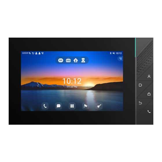
The i55A & i55A-Z is stylish and simple in appearance, with different decoration styles. It has a 7-inch capacitive touch screen, sensitive touch control, precision and no dead Angle. It is built with 1.5W dual speakers and AEC algorithm to achieve high-quality two-way hands-free calls. -
Page 15: Packing Contents
4.2 Packing Contents... -
Page 16: Install Guide
POE switch and external power adapter, device will get power supply from POE switch in priority, and change to external power adapter once the POE power supply fails. Please use the power adapter supplied by Fanvil and the PoE switch met the specifications to ensure the device work properly. -
Page 17: Installation
5.2 Installation External Device Connection Diagram 5.2.1 Picture 1 - External Device Picture 2 - Device Connection Table 1 - Status Prompt and Notification Icons Description Interface Power interface: 12V/1A input. ① Ethernet interface: standard RJ45 interface, 10/100M adaptive, ② it is recommended to use CAT5 or CAT5E network cable. - Page 18 2 sets of short-circuit output interfaces: corresponding to the ③-1 short-circuit input interface, login device webpage settings, can be connected to electric locks, alarms etc. 1 sets of doorbell interfaces. ③-2 1 sets of RS485 interfaces. ③-3 Power interface: 12V/1A input. ④...
-
Page 19: Appendix Table
Appendix Table 6.1 Appendix I - Icon Table 2 - Keypad Icons Management Center(Only i55A & i55A-Z ) Video Monitoring (Only i55A & i55A-Z ) Answer(Only i55A & i55A-Z ) Return/Hang up(Only i55A & i55A-Z ) Unlock(Only i55A & i55A-Z )... - Page 20 Connecting WIFI WIFI network anomaly Open Bluetooth SIP Hotspot Miss Calllog Unread voice message Enable Restricted Incoming List Enable Allowed Incoming List Enable Restricted Outgoing List Table 4 - DSSkey Icons Translate 图标 Line Speed Dial Intercom Voice Message Call forward Key Event/DND...
- Page 21 Key Event/Call Hold Key Event/Phonebook Key Event/Redial Key Event/Pickup Key Event/Auto Redial On Key Event/Auto Redial Off Key Event/Call Forward Key Event/Call Logs Key Event/Flash Key Event/Headset Key Event/Release Key Event/SMS Key Event/Call Back Key Event/Hide DTMF Key Event/Power Light Key Event/Prefix Key Event/Hot Desking Key Event/End...
-
Page 22: Appendix Ii - Application Icons
Key Event/Escalate Key Event/Trace Key Event/Handfree Key Event/Answer Key Key Event/Private Hold Local Contact & LDAP Contact & XML Contact & Broadsoft Contact Record URL & Action URL & XML Browser DTMF BLF List Multicast 6.2 Appendix II - Application Icons Click this icon to enter the pre-dial interface, and then dial the number using the screen or keyboard. - Page 23 Supports search, add, delete, and edit contacts. Contact Support access to various websites. Call and non-call recording is supported, and export is supported. Recorder Display and view dates, create activity alerts, and more. Calendar Including basic Settings, call Settings, advanced Settings and about the device and other four major options, you can set the corresponding menu System Settings (this setting is the Android system built-in Settings).
-
Page 24: Appendix Iii - Indicator Light
Apply List Memory acceleration, garbage removal, auto-start management, and software management can be set in the corresponding menu. Equipment Housekeeper 6.3 Appendix III - Indicator Light Type Status Indicate Ringing Default blue flash,Settable Keep Default off,Settable Mute Default off,Settable indicator light Call/Dial Default off,Settable Default blue slow flash,Settable... -
Page 25: Introduction To The User
Introduction to the User 7.1 Instruction of Keypad i55A&i55A-Z Key description 7.1.1 Picture 3 - Key description The picture above shows the key layout of the device. Each key provides its own specific functions. Users can operate the device by referring to the instructions of the keys in the illustrations in this section. -
Page 26: I57A&I57A-Z Key Description
i57A&i57A-Z Key description 7.1.2 Picture 4 - Key description The picture above shows the key layout of the device. Each key provides its own specific functions. Users can operate the device by referring to the instructions of the keys in the illustrations in this section. -
Page 27: Idle Screen
The device supports sliding up and down. Slide down the standby home page to view the network connection information, date time and other information of the device;Slide up to exit the above information interface. Right slide can expand DSSkey, full screen display custom shortcut key information;Slide left to exit the above interface. -
Page 28: Device Status
:application keys, users can operate the device through the application. :displays the time and date, which can be changed by setting the time zone, etc. :application keys, users can operate the device through the application. Icon description is described in 6.2 Appendix II. -
Page 29: Web Management
Picture 7 - WEB device status 7.5 Web Management Users can use the web page of the device to manage and operate the device. Users first need to enter the IP address of the device in the browser and open the web page of the device. The user can view the IP address of the device by pressing [Device setting] >... -
Page 30: Network Configurations
name and password are "admin". For the specific details of the operation page, please refer to page 11 Web configurations. 7.6 Network Configurations The device supports two kinds of network connection modes: wired network connection and wireless network connection. This section describes the wired network connection. For wireless network connection, refer to 10.5 wi-fi. - Page 31 service provider and the account information used for registration and authentication. When the device is applied with the configuration, it will register the device to the service provider with the server's address and user's authentication as stored in the configurations. The user can conduct line configuration on the interface of the device or the webpage, and input the corresponding information at the registered address, registered user name, registered password and SIP user, display name and registered port respectively, which are provided by the SIP server...
- Page 32 Picture 10 -Device display name and port WEB interface:After logging into the device page, enter [Line] >> [SIP] and select SIP Line for configuration, click apply to complete registration after configuration, as shown below: Picture 11 -Web SIP registration...
-
Page 33: Basic Function
8 Basic Function 8.1 Making Phone Calls Dialing Methods User can dial a number by, Entering the number from dialer Selecting a phone number from phonebook contacts (Refer to 10.2 Local contacts) Selecting a phone number from cloud phonebook contacts (Refer to 10.2.3 Cloud Phone ... -
Page 34: Answering Calls
Picture 13 - Call number 8.2 Answering Calls When the device is idle and there is an incoming call, the user will see the following incoming call reminder screen. Picture 14 - Answering calls User can answer the call by press the [Video answer] button. -
Page 35: Talking
Talking 8.2.1 8.2.1.1 Voice Call When the call is connected, user will see a talking mode screen as the following figure. Picture 15 - Talking interface Table 8 - Talking mode Number Name Description The current line The line currently used by the device. ①... -
Page 36: Make / Receive The Second Call
Picture 16 - Device video interface Table 9 - Video call mode Number Name Description ① Call Transfer Transfer the incoming number to another number. For details, please refer to 8.11 Call Forward ② Dial During the call, enter the door opening password of the access control equipment to open the door. - Page 37 The Second Incoming Call When there is another incoming call during talking a phone call, this call will be waiting for user to answer it. User will see the call message in the middle of current screen. The device will not be ringing but playing call waiting tone in the audio channel of the current call and the LED will be flashing in green.
-
Page 38: End Of The Call
the hold icon in the avatar position. Ending One Call The user can hang up the current call by pressing the [Hang up] button. The device will return to the hold state in single call mode. The user can also press the [Resume] key to resume the current call. -
Page 39: Open The Door During The Call
Note! URL format of door lock: http:// device Username: password @ device IP address /cgi-bin/ConfigManApp.com?key=F_LOCK&code= remote door opening password (this URL format is only limited to our products) Picture 20 - Add door lock Open the door during the call 8.4.3 Input DTMF ... - Page 40 Picture 21 - Add the parameter setting diagram of access control equipment Table 10 - Add description of access control parameters Number Name Remarks ① name Set the name of access control ② number Set the number of access control ③...
-
Page 41: Monitor
8.5 Monitor Click the [Monitor] icon to enter the monitoring video interface, where you can see the information of the bound video screen, and turn the page of the video by sliding left / right. Note! The camera device added by scanning needs to turn on the ONVIF function! Configure on the device side 8.5.1 The video information can be added, edited, modified and deleted on the device side. - Page 42 Picture 24 - Fill in monitoring equipment parameters Add manually The user enters the [Monitor] interface, and clicks the Add icon in the interface to pop up the window of adding equipment. The user fills in according to the parameter description, and then clicks [NEXT] to complete the adding operation of the equipment.
-
Page 43: Arming(Input Setting
8.6 Arming(Input Setting) Users can directly click the security icon in the standby interface to pop up the selection of security mode, as shown in the figure. Users can click the mode they want to switch, enter the current security password (123456 by default), click [OK] to switch successfully, and the screen icon will also become the corresponding security icon. -
Page 44: Zone Setting
Picture 27 - Security settings Set on the web side Users can set security mode, select input port and trigger mode in [Web] > > [Security Settings] > > [Input Settings]. Please refer to for specific parameter descriptions11.40 Security Settings Picture 28 - Web configuration Zone setting 8.6.2... -
Page 45: View Security Log
setting interface, and set the security zone of the device according to the interface parameters. Picture 29 - Defense zone setting View security log 8.6.3 The user can view the security alarm log in the [Message] interface, and can edit and delete the security alarm log. -
Page 46: Sos
8.7 SOS In the standby interface, the user can click the icon to make a one button call to the set emergency number. When setting numbers, each emergency number is separated by an English comma. Configure on the web side ... -
Page 47: Mute The Call
not heard. Normally, mute mode will be automatically turned off at the end of a call. You can also turn on mute on any screen (such as the free screen) and mute the ringtone automatically when there is an incoming call. Mute mode can be turned on in all call modes . -
Page 48: Call Hold/Resume
Picture 34 - Ringtone mute Cancel ringing tone mute: in the standby or incoming interface, press the device volume increase button again or select the ringing tone icon to pull up the volume to increase or decrease the volume to cancel ringing tone mute. After cancellation, the mute icon will no longer be displayed in the lower right corner. -
Page 49: Dnd
Picture 35 - Call hold 8.10 User may enable Do-Not-Disturb (DND) feature on the device to reject incoming calls (including call waiting). The DND can be enabled on line basis. Enable/Disable device all lines DND, Methods the following: Device interface:Default standby mode, ... - Page 50 Picture 36 - Enable DND If the user wishes to enable/disable the uninterrupted function on a specific line, the user can set the uninterrupted function on the page of configuring the line. 1) Press [Device Settings] > > [Call] > > [DND] to enter the editing page of DND. 2) Select the line through the left / right navigation keys to adjust the disturbance free mode and status, Press the [Save] button to save after completion.
- Page 51 The user can also use the DND timer. After the setting, the DND function will be automatically turned on and the DND icon will turn red in the time range. Picture 38 - DND timer WEB interface: Enter [Device setting] >> [Features] >> [DND Settings], set the DND type ...
-
Page 52: Call Forward
Picture 40 - Line DND 8.11 Call Forward Call forward is also known as ‘Call Divert' which is to divert the incoming call to a specific number based on the conditions and configurations. User can configure the call forward settings of each line. There are three types, Unconditional Call Forward –... - Page 53 Picture 41 - Select the line to set up call forwarding 3) Click the slide button to select on/off. 4) Configure parameters by clicking on the text box and enter the required information. After completion, press the [Save] button to save the changes. WEB interface:Enter [Line] >>...
-
Page 54: Call Waiting
Picture 43 - Call forwarding rendering 8.12 Call Waiting Enable call waiting: new calls can be accepted during a call. Disable call waiting: new calls will be automatically rejected and a busy tone will be prompted. Enable call waiting tone: when you receive a new call on the line, the tone will beep. ... -
Page 55: Dial-Up Query
Picture 45 - Web call waiting tone setting 8.13 Dial-up Query Device is defaulted to open the dial-up inquiry function, dial-out, enter two or more Numbers, dial the interface will automatically match call records, contacts in the number list, touch the number that you select to call out. -
Page 56: Anonymous Call
Log in the device page, enter [Line] >> [SIP], select [SIP] >> [Basic settings], start auto-answering, and click apply after setting the automatic answering time. Picture 47 - Web page to start auto-answering 8.15 Anonymous Call Anonymous Call 8.15.1 The Device can set up anonymous calls to hide the calling number and the calling name. The default is none, which is off, and RFC3323 and RFC3325 are optional. -
Page 57: Hotline
Picture 49 - Page Settings blocking anonymous call 8.16 Hotline Support hot line dialing. After setting the hot line dialing, the device will call automatically according to the delay time of the hot line. On the website [Line] >> [SIP] >> [Basic Settings], can also set up a hotline. ... -
Page 58: Advance Function
9 Advance Function 9.1 Intercom When the Intercom is enabled, it can automatically receive calls from the intercom. Picture 51 - Web Intercom configure Table 11 - Intercom configure Parameter Description Enable Intercom When intercom is enabled, the device will accept the incoming call request with a SIP header of Alert-Info instruction to automatically answer the call after specific delay. -
Page 59: Message
Picture 52 - Multicast Settings Page Table 12 - MCAST Parameters on Web Parameters Description Normal Call Priority Define the priority of the active call, 1 is the highest priority, 10 is the lowest. Enable Page Priority The voice call in progress shall take precedence over all incoming paging calls. -
Page 60: Sms
9.3.1 Picture 53 - SMS Send messages: Go to [Message] >> [SMS]. Users can create new messages, select lines and send numbers. After editing is complete, click Send. View SMS: Use the navigation keys to select the standby icon [Message] ... - Page 61 Picture 54 - New Voice Message Notification To listen to a voice message, the user must first configure the voicemail number. After the voicemail number is configured, the user can retrieve the voicemail of the default line. When the device is in the default standby state, the pull-down status bar displays the number of unread voice messages, and the voice ...
-
Page 62: Hotspot
9.4 Hotspot SIP hotspot is a simple but practical function. With simple configurations, the SIP hotspot function can implement group ringing. SIP accounts can be expanded. Set a device as a SIP hotspot and other devices (B and C) as SIP hotspot clients. When somebody calls device A, device A, B, and C all ring. - Page 63 Fill in the custom hotspot communication port. The server and client ports Local port need to be consistent Fill in the name of the SIP hotspot, this configuration is used to distinguish Name different hotspots under the network to avoid connection conflicts Set whether to associate the SIP hotspot function on the corresponding SIP Line settings line...
-
Page 64: Record
9.5 Record The device supports recording during a call. Local Record 9.5.1 When using local recording, it is necessary to start recording on the device page [Application] >> [Manage recording], select the local type and set the voice coding. The webpage is as follows: Picture 59 - WEB local recording Local recording steps:... -
Page 65: Server Record
The web is as follows: Picture 60 - Web server recording Note: to be used with Fanvil recording software. SIP INFO Record 9.5.3 The device is registered with a server that supports SIP INFO recording. -
Page 66: Device Settings
10 Device Settings 10.1 Basic Settings Language 10.1.1 The user can set the device language through the device interface and web interface. Device interface:After resetting the factory settings, the user needs to set the language; when setting the language during standby, go to [Device Settings] >> [Basic] >> [Language&Input] Settings, as shown in the figure. -
Page 67: Time & Date
Picture 63 - Language setting on Web page The function box on the right side of the web interface language setting box is “Synchronize language to device”; if selected, the device language will be synchronized with the webpage language. If it is not selected, it will not be synchronized. Time &... - Page 68 Picture 64 - Set time & date on device Web interface: Log in to the device webpage and enter [Device Settings] >> [Time/Date] , as shown in the figure: Picture 65 - Set time & date on web page Table 14 - Time Settings Parameters Parameters Description...
-
Page 69: Screen
default enabled. Manual: User can modify data manually. SNTP Server SNTP server address Time zone Select the time zone Time format Select time format from one of the followings: 1 JAN, MON 1 January, Monday JAN 1, MON ... -
Page 70: Brightness And Backlight
Picture 66 - Set screen parameters on device 10.1.3.1 Brightness and backlight Device interface: 1) in standby mode, slide from the top edge of the screen to enter the status bar;Sliding down again makes it easy to set the brightness of the device. 2) the device enters [System Setting] >>... -
Page 71: Ring
Picture 67 - screen saver Ring 10.1.4 When the device is in the default standby mode, Enter [Device Settings] >> [Basic] >> [Sound] item till you find [Tone] item. Enter [Sound] >> [Tone] set promote tone The prompt tone contains Settings such as device Ringtone, Notification Tingtone, Screen ... -
Page 72: Phone Book
10.2 Phone book Local contact 10.2.1 Users can save the contact information in the phonebook and dial the phone number of the contact directly in the phonebook. The user can open the phonebook by pressing the function menu key [contact] or the preset key [phonebook] on the device in the default main interface. By default, the phonebook is empty, and users can add contacts to the phonebook manually or from the call record (or cloud phonebook). - Page 73 Contact Name Tel. Number Mobile Number Home Number Work Number Main Number Work Fax Home Fax Pager Other Number Custom Line Contact Group Photo Ring Tone ...
-
Page 74: Add / Edit / Delete Group
10.2.1.2 Add / Edit / Delete Group By default, the group list is empty. Users can create their own group, edit group names, add or remove contacts from the group, and delete groups. Add group. In the contact list interface, press the "group" icon to switch to the group list. Click ... -
Page 75: Cloud Phone Book
It is also a useful tool to synchronize his/her phonebook from a personal mobile phone to the device with Fanvil Cloud Phonebook Service and App which is to be provided publicly soon. -
Page 76: Downloading Cloud Phone Book
Open cloud phonebook list, press [Application] >> [Contacts] >> [Network PhoneBook] in phonebook screen. TIPS! The first configuration on cloud phone should be completed on Web page by selecting [PhoneBook] >> [Cloud Contacts]. The setting of addition/deletion on device could be done after the first setting on Web page. -
Page 77: Call Log
Picture 74 - Browsing Contacts in Cloud Phone book 10.3 Call Log The device can store up to 1000 call log records and user can open the call logs to check all incoming, outgoing, and missed call records by pressing [CallLog] icon. In the call logs screen, user may browse the call logs with up/down navigator keys. - Page 78 Picture 75 - Call Log Users can also filter the call records of specific call types to narrow down the scope of search records, and select a call record type by left and right navigation keys. Missed - Missed Call Log Incoming - Incoming Call Log Outgoing - Outgoing Call Log Forward - Forward Call Log...
-
Page 79: Function Key
10.4 Function Key Function key Settings: It shows 4 DSSKEY keys in standby mode on the Screen, each of which can be customized (expansion keys are not supported). Users can customize and configure each DSSKEY key on each page. Users can add/delete DSSkey pages through the webpage, and can use the page switch key to switch DSSkey pages. -
Page 80: Wi-Fi
MCAST Paging MCAST Listening Action URL XML Browser Moreover, user also can add the user-defined title for the DSS Keys, which is configured as Memory Key / Line / URL / MCAST Paging / Prefix. NOTICE! User-defined title is up to 10 characters. More detailed information refers to 11.31 Function key >>... -
Page 81: Snap
Picture 79 - WIFI settings ( 2 ) 10.6 Snap When the user is in the process of video call or when the call is missed due to timeout, the device will perform the function of capturing pictures. During the video call, the user can click the icon on the left to take a screenshot of the ... -
Page 82: Advanced
Picture 81 - Snapshot picture display 10.7 Advanced Line Configurations 10.7.1 Device access [Device settings] >> [Account] , select [Register Account] to configure the SIP line on the device. Picture 82 - SIP address and account information... -
Page 83: Network Settings
For users who want to configure more options, user should use web management portal to modify or [More Register Settings] in accounts on the individual line to configure those options. Network Settings 10.7.2 10.7.2.1 Network Settings Device access [Device Settings] >> [Advanced] >> [Ethernet], you can configure the SIP line on the device. -
Page 84: Web Server Type
Picture 84 - Static IP network mode When using Static IP mode, user must configure the IP address manually. IP Address:Device IP address. Subnet Mask: sub mask of your LAN. IP Gateway:The gateway IP address. Device could access the other network via it. ... -
Page 85: Set The Secret Key
Picture 85 - The device configures the web server type Set The Secret Key 10.7.3 The device is in the default standby state, find [Device Settings] > > [Advanced] > > [Password] in the application. Click to enter [Menu] to change the password of the menu and security mode. ... - Page 86 Picture 87 - Page auto provision Settings Fanvil devices support SIP PnP, DHCP options, Static provision, TR069. If all of the 4 methods are enabled, when the terminal starts, the configuration obtained first will be used for automatic deployment according to the order of obtaining the configuration.
- Page 87 When the feature is enable, if the configuration of server is Enable Server Digest changed, Device will download and update. DHCP Option Confiugre DHCP option, DHCP option supports DHCP custom Option Value option | DHCP option 66 | DHCP option 43, 3 methods to get the provision URL.
-
Page 88: Factory Reset
ACS Server Type There are 2 options Serve type, common and CTC. ACS Server URL ACS server address ACS User ACS server username (up to is 59 character) ACS Password ACS server password (up to is 59 character) Enable TR069 Warning If TR069 is enabled, there will be a prompt tone when Tone connecting. -
Page 89: Web Configurations
11 Web Configurations 11.1 Web Page Authentication The user can log into the web page of the device to manage the user's device information and operate the device. Users must provide the correct user name and password to log in. 11.2 System >>... -
Page 90: System >> Upgrade
TR069:TR069 related configuration MMI: MMI module, including authentication user information, web access protocol, etc. DSS Key: DSS Key configuration Basic Network Clear Tables Select the local data table to be cleared, all selected by default. Reset Device The device data will be cleared, including configuration and database tables. 11.5 System >>... -
Page 91: System >> Auto Provision
server (HTTP server). When the primary server is unavailable, request the backup server. The web page starts to automatically detect the upgrade and configure the interval. If the server has a new Upgrade Interval version, the device will prompt for the upgrade at the interval. -
Page 92: Network >> Basic
11.9 Network >> Basic This page allows users to configure network connection types and parameters. 11.10 Network >> Service Port This page provides settings for Web page login protocol, protocol port settings and RTP port. Picture 91 - Service Port Settings Table 17 - Service port Parameter Description... -
Page 93: Line >> Sip
quality of the device service. For configuration, query the 10.7 advanced Settings. 11.12 Line >> SIP Configure the Line service configuration on this page. Table 18 - Line configuration on the web page Parameters Description Register Settings Line Status Display the current line status at page loading. To get the up to date line status, user has to refresh the page manually. - Page 94 answered it Call Forward Unconditional Enable unconditional call forward, all incoming calls will be forwarded to the number specified in the next field Call Forward Number Set the number of unconditional call forward Unconditional Call Forward on Busy Enable call forward on busy, when the device is busy, any incoming call will be forwarded to the number specified in the next field.
- Page 95 DTMF SIP INFO Mode Set the SIP INFO mode to send ‘*' and ‘#' or ‘10' and ‘11' Enable DND Enable Do-not-disturb, any incoming call to this line will be rejected automatically Subscribe For Voice Message Enable the device to subscribe a voice message waiting notification, if enabled, the device will receive notification from the server if there is voice message waiting on the server Use VPN...
- Page 96 Disable Blocking Anonymous Set the feature code to dial to the server Call Call Waiting On Code Set the feature code to dial to the server Call Waiting Off Code Set the feature code to dial to the server Send Anonymous On Code Set the feature code to dial to the server Send Anonymous Off Code Set the feature code to dial to the server...
- Page 97 Convert URI Convert not digit and alphabet characters to %hh hex code Use Quote in Display Name Whether to add quote in display name, i.e. “Fanvil” vs Fanvil Enable GRUU Support Globally Routable User-Agent URI (GRUU) Sync Clock Time...
-
Page 98: Line >> Sip Hotspot
PTime(ms) Set whether to bring ptime field, default no. Packing time Set the packaging time, unit: milliseconds, optional values: 10, 20, 30, 40, 50, 60 Transaction timer T1 Configure the duration of SIP transaction timer T1, unit: milliseconds, range: 500-10000 Transaction timer T1 Configure the duration of SIP transaction timer T1, unit: milliseconds, range: 2000-40000... - Page 99 number to dial out; Dial Fixed Length The number entered by the user is automatically dialed out when it reaches a fixed length Timeout dial The system dials automatically after timeout Enable E.164 Please refer to e. 164 standard specification Add dialing rules: Picture 93 - Custom setting of dial - up rules Table 20- Dial-up rule configuration table...
- Page 100 all: xxx – xxx will replace the phone number. add: xxx – xxx will be dialed before any phone number. del –The characters will be deleted from the phone number. rep: xxx – xxx will be substituted for the specified characters. ...
-
Page 101: Line >> Action Plan
11.15 Line >> Action Plan When calling to a phone, the bounded IP camera synchronously transmits video to the opposite phone (video support). Log in to the device web, visit [Line] >[Action plan], and configure action plan rules. Picture 96 - Action Plan Table 21 - Action Plan Parameter Description... -
Page 102: Device Settings >> Features
Server Address Set the STUN server address Server Port Set the STUN server port, default is 3478 Binding Period Set the STUN binding period which can be used to keep the NAT pinhole opened. SIP Waiting Time Set the timeout of STUN binding before sending SIP messages Certification File TLS Certification File... - Page 103 Enable Restricted Incoming List Whether to enable restricted call list. Enable Allowed Incoming List Whether to enable the allowed call list. Enable Restricted Outgoing List Whether to enable the restricted allocation list. Enable Country Code Whether the country code is enabled. Country Code Fill in the country code.
- Page 104 Call number filtering Automatically resume If the current road changes, it will automatically release hold current call If the remote device fails to answer within the time, the local end Call timeout will automatically hang up Ringing timeout Enable push XML authentication Enable push XML authentication If the subscribed BLF number has an incoming call, whether to Display the grab prompt window display the prompt interface of snap in...
- Page 105 Redial Settings Enable Call Completion Enable Auto Redial Auto Redial Interval valid value:1-180. Auto Redial Times valid value:1-100. Redial Enter CallLog Response Code Settings DND Response Code Set the SIP response code on call rejection on DND Busy Response Code Set the SIP response code on line busy Reject Response Code Set the SIP response code on call rejection...
-
Page 106: Device Settings >> Media Settings
off / on / Slowblink/Fastblink, which is off by default Notification Popups No incoming call popup prompt after opening, no popup prompt Display Missed Call Popup when closing, open by default. Voice message popup prompt is not answered after opening, Display MWI Popup and it is opened by default if there is no popup prompt when closing. - Page 107 Table 24- Voice settings Parameter Description Codecs Settings Select enable or disable voice encoding: G.711A/U,G.722,G.729, G.726-16,G726-24,G726-32,G.726-40, ILBC,opus Video codec Video codec Select to enable video encoding:H264 Media Setting DTMF Payload Type Enter the DTMF payload type, the value must be 96~127. Headset Mic Gain Set the Headset's radio volume gain to fit different models of Headsets.
-
Page 108: Device Settings >> Mcast
11.19 Device settings >> MCAST This feature allows user to make some kind of broadcast call to people who are in multicast group. User can configure a multicast DSS Key on the device, which allows user to send a Real Time Transport Protocol (RTP) stream to the pre-configured multicast address without involving SIP signaling. -
Page 109: Device Settings >> Time/Date
Picture 97 - Action URL 11.21 Device settings >> Time/Date The user can configure the time Settings of the device on this page. Table 26 - Time & Date settings Parameters Description Network Time Server Settings Time Synchronized via SNTP Enable time-sync through SNTP protocol Time Synchronized via DHCP Enable time-sync through DHCP protocol... -
Page 110: Device Settings >> Time Plan
Local Choose your local, device will set daylight saving time automatically based on the local DST Set Type Choose DST Set Type, if Manual, you need to set the start time and end time. Fixed Type Daylight saving time rules are based on specific dates or relative rule dates for conversion. -
Page 111: Device Settings >> Tone
Picture 98 - Time plan 11.23 Device settings >> Tone This page allows users to configure a device prompt. You can either select the country area or customize the area. If the area is selected, it will bring out the following information directly. If you choose to customize the area, you can modify the button tone, call back tone and other information. -
Page 112: Phonebook >> Contact
Configure Greeting Words The greeting message will display on the top left corner of the LCD when the device is idle, which is limited to 16 characters. The default chars are ‘VOIP PHONE’. 11.25 Phonebook >> Contact User can add, delete, or edit contacts in the phonebook in this page. User can browse the phonebook and sorting it by name, phones, or filter them out by group. -
Page 113: Phonebook >> Call List
User must configure the LDAP Server information and Search Base to be able to use it on the device. If the LDAP server requests an authentication, user should also provide username and password. To configure a LDAP phonebook, the following information should be entered, Display Title (must) LDAP Server Address (must) LDAP Server Port (must) -
Page 114: Phonebook >> Web Dial
Restricted Outgoing Calls: Adds a number that restricts outgoing calls and cannot be called until the number is removed from the table. 11.28 Phonebook >> Web Dial Use web pages for call, reply, and hang up operations. 11.29 Phonebook >> Advanced Users can export the local phone book in XML, CSV, and VCF format and save it on the local computer. - Page 115 Table 28 - Function Key configuration Parameters Description BLF (NEW CALL/BXFE /AXFER): It is used to prompt user the Memory Key state of the subscribe extension, and it can also pick up the subscribed number, which help user monitor the state of subscribe extension (idle, ringing, a call).
-
Page 116: Function Key >> Softkey
11.32 Function Key >> Softkey The User Settings mode and display style, display page. Table 29 - Softkey configuration Parameter Description Softkey Mode Softkey mode Disabled and More,Default is Disabled Softkey Style Softkey display style Softkey Exit on Left or Right Screen Redial/2aB/Delete/Exit/Forward/Local Contacts/CallLog Divert Dialed... -
Page 117: Application >> Manage Recording
Picture 101 - IP Camera List 11.34 Application >> Manage Recording 9.5 Record for details of recording. 11.35 Security >> Web Filter The user can set up a configuration management device that allows only machines with a certain network segment IP access. Picture 102 - Web Filter settings Picture 103 - Web Filter settings Add and remove IP segments that are accessible;... -
Page 118: Security >> Trust Certificates
configure the filter segment of the web page to be outside your own network segment, otherwise you will not be able to log in the web page. 11.36 Security >> Trust Certificates Set whether to open license certificate and general name validation, select certificate module. You can upload and delete uploaded certificates. -
Page 119: Security >> Firewall
11.38 Security >> Firewall Picture 106 - Network firewall Settings Through this page can set whether to enable the input, output firewall, at the same time can set the firewall input and output rules, using these Settings can prevent some malicious network access, or restrict internal users access to some resources of the external network, improve security. -
Page 120: Device Log >> Device Log
The destination address can be either the specific IP address Dst Address or the full address 0.0.0.0; It can also be a network address similar to *.*.*.0, such as: 192.168.1.0. Is the source address mask. When configured as Src Mask 255.255.255.255, it means that the host is specific. - Page 121 alarm bell. Picture 109 - Security settings ( 1 ) Picture 110 - Security settings ( 2 ) Table 31- Security Settings Security Settings Parameters Description...
- Page 122 Basic Settings Ringtone Duration Set the ringtone duration, default value is 5 seconds. Set remote server address. The device will send message to the server when the alarm is triggered. The message format is : Input & Tamper Alarm_Info:Description=i16SV;SIP Server Address User=;Mac=0c:38:3e:3a:06:65;IP=;...
- Page 123 By duration: Reset the output port status when output duration occurs. By state: Reset the output port status when device’s call state changes. Enable or disable trigger by URI. User can send commands from remote device or server to i16SV Trigger by URI series device, if the command is correct, then device will trigger corresponding output port.
-
Page 124: Trouble Shooting
12 Trouble Shooting When the device is not in normal use, the user can try the following methods to restore normal operation of the device or collect relevant information and send a problem report to Fanvil technical support mailbox. 12.1 Get Device System Information Users can get information by pressing the [Device Settings] >>... -
Page 125: Network Packets Capture
Picture 111 - Screenshot 12.5 Network Packets Capture Sometimes it is helpful to dump the network packets of the device for issue identification. To get the packets dump of the device, user needs to log in the device web portal, open page [System] >> [Tools] and click [Start] in “Network Packets Capture”... -
Page 126: Export Debug Data
Picture 112 - Web capture User may examine the packets with a packet analyzer or send it to Fanvil support mailbox. 12.6 Export Debug Data When encountering abnormal problems, log information is helpful. Users can export debugging information with one click on the web page. After a while, send the exported compressed package to fanvil technical support mailbox and describe the problem in detail. - Page 127 1. The device is powered by external power supply via power adapter or PoE switch. Please use standard power adapter provided by Fanvil or PoE switch met with the specification requirements and check if device is well connected to power source.
Need help?
Do you have a question about the i55A and is the answer not in the manual?
Questions and answers