
Related Manuals for Fanvil i504 Series


Summary of Contents for Fanvil i504 Series
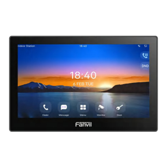
- Page 1 i504x&i505x&i506W&i507W Series Indoor Station Quick Installation Guide i506W i507W i504/i504W i505/i505W...
-
Page 2: Physical Specification
Package Contents Wall-mount Bracket Quick Installation Guide Indoor Station TA4*30mm Screw*4 2*3 pin Cable*3 Screw Fixing Seat*4 PM4*16mm Screw*2 TM6#*20mm Screw*4 KM3*30mm Screw*2 Physical specification Model Device Dimension i504x&i505x 177.38 x 113.99 x 22.5 (mm) i506W&i507W 247.96 x 156.96 x 25.6 (mm) Product appearance description Panel i504x&i505x... - Page 3 i506W&i507W Speaker Interface description There are some interfaces on the back of the device for connecting power supply, alarms etc. The connections are as follows: ② ③ Interface Description Power interface:12V/1A input Ethernet interface: standard RJ45 interface, 10/100M adaptive, it is recommended to use CAT5 or CAT5E network cable Power interface:12V/1A input...
-
Page 4: Installation Diagram
1 sets of doorbell interfaces 1 sets of short-circuit output interfaces: corresponding to the short-circuit input interface, login device webpage settings, can be connected to electric locks, alarms etc. 8 sets of alarm input interfaces: input devices for connecting switches, infrared sensor, door sensor, vibration sensors etc. 1 sets of RS485 interfaces: can be connected to card reader, sensor etc. - Page 5 C. Fix the wall bracket on the wall with four TA4X30 screws With 86 embedded box in the wall Fix the wall bracket on the 86 embedded box with two PM4X16 screws Step 2. Connect peripherals A. If you need to connect other input and output devices, please connect to the host through the cable Step 3.
- Page 6 Step 2:Add the SIP account. Set SIP server address, port, user name, password and SIP user with assigned SIP account parameters. Select “Activate”, and then click Apply to save this setting. Step 3:Unlock Setting Application——Door phone Settings——Add——OK. Title: Door Phone mode Number: The SIP account of DoorPhone Line: The SIP line of Indoor Unit Access codec: Consistent with the access code in doorphone access table (The i50x as calling party)
-
Page 7: Unlock The Door
7. Local Operation 6.1 Answer/hang up calls When the door phone calls the indoor unit, click the button to answer the call, and click the button to hang up the call. 6.2 Unlock the door During the call of indoor unit and door phone, click the button to unlock the door.
Need help?
Do you have a question about the i504 Series and is the answer not in the manual?
Questions and answers