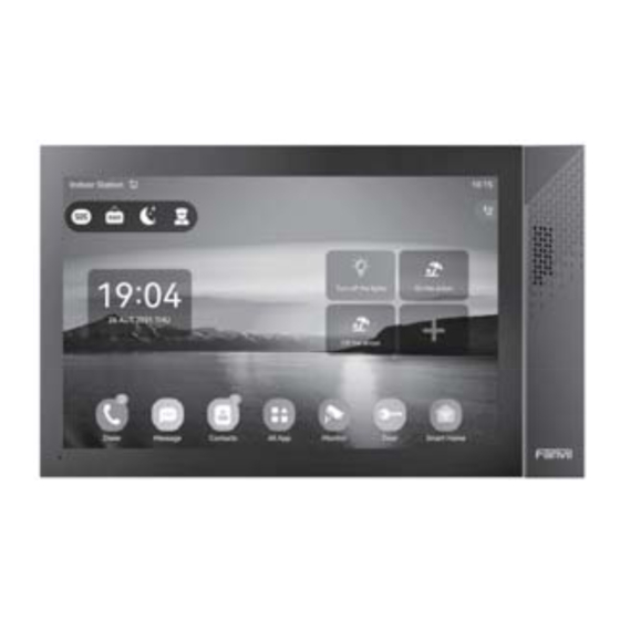
Summary of Contents for Fanvil i55A-Z
- Page 1 Indoor Station Quick Installation Guide i55A&i55A-Z i57A&i57A-Z...
-
Page 2: Package Contents
Screw*5 Screw*3 Physical specification Model Device Dimension i55A&i55A-Z 217*124*21 (mm) 295*181*24 (mm) i57A&i57A-Z Product appearance description 1) Panel a) i55A&i55A-Z LED indicator Speaker 2 Speaker 1 Manager center key Unlock key Answer key Return / Hang up key Monitor key... - Page 3 b) i57A&i57A-Z LED indicator 1 Power Speaker Volume +/- LED indicator 2 2) Interface description There are some interfaces on the back of the device for connecting power supply, alarms etc. The connections are as follows: Description Interface Power interface: 12V/1A input. Ethernet interface: standard RJ45 interface, 10/100M adaptive, it is recommended to use CAT5 or CAT5E network cable.
-
Page 4: Installation Diagram
3) External device connection diagram Switch WAN Port Output Port Input Port Electric lock Door Magnetic Infrared Sensor Output Port Switch Input Port Alarm light Vibration Sensor Emergency Key Installation Diagram Wall bracket (DIM:mm) Model 1: Wall-mounted Installation (CN:86 embedded box,US: single gang&Dual gang, EUR:80 embedded box) Step 1: Install wall bracket Without 86 embedded box in the wall A. - Page 5 IP Indoor Unit Setting Step 1: Log in the web setting page of Indoor Unit Input IP address of indoor unit (e.g. http:// 172.18.90.14) into the address bar of PC’s web browser. The default user name and password are both admin. Step 2: Add the SIP account Set SIP server address, port, user name, password and SIP user with assigned SIP account parameters.
-
Page 6: Local Operation
(Only support for the communication with video doorphone) 6.4 Volume adjustment When the indoor unit is talking to other devices like doorphone, click the button to increase the volume, and click the button to decrease the volume. Fanvil Technology Co., Ltd Website: www.fanvil.com EMail: sales@fanvil.com support@fanvil.com...


Need help?
Do you have a question about the i55A-Z and is the answer not in the manual?
Questions and answers