Sign In
Upload
Download
Table of Contents
Contents
Add to my manuals
Delete from my manuals
Share
URL of this page:
HTML Link:
Bookmark this page
Add
Manual will be automatically added to "My Manuals"
Print this page
×
Bookmark added
×
Added to my manuals
Manuals
Brands
Parker Manuals
Industrial Equipment
SPD 2
User manual
Parker SPD 2 User Manual
Hide thumbs
1
2
3
Table Of Contents
4
5
6
7
8
9
10
11
12
13
14
15
16
17
18
19
20
21
22
23
24
25
26
27
28
29
30
31
32
33
34
35
36
37
38
39
40
41
42
43
44
45
46
47
48
49
50
51
52
53
54
55
56
57
58
59
60
61
62
63
64
65
66
67
68
69
70
71
72
73
74
75
76
77
78
79
80
81
82
83
84
85
86
87
88
89
90
91
92
93
94
95
96
97
98
99
100
101
102
103
104
105
106
107
108
109
110
page
of
110
Go
/
110
Contents
Table of Contents
Troubleshooting
Bookmarks
Table of Contents
Table of Contents
Introduction
General Information
Product Description
Main Software Features
Expansibility: the Parker-S.B.C. Bridge and Its Philosophy
Support Tools
Conformity to EMC Standards
Safety
Data for the UL Certification
Mechanical Dimensions
Technical Specifications
Connectors and Terminal Boards
SPD 2, 5 and 8
SPD 16 E 25
Installation and Safety Instructions
How to Suppress Interference
Grounding and Screening
Filters
Further Suggestions
Power Connections
Motor Cable
Protection Fuse and Power Supply Cable
Signal Cables
Resolver Cable
Signal Cables Connection
Power Connection Diagrams
Power Connection Diagrams for SPD16 and SPD25
Power Connection Diagrams for SPD2, SPD5 E SPD8
Signal Connection Diagrams
Serial Line Connection
Frequency Input/Output Connection
CANBUS Connection
Incremental Encoder Connection
Heidenhain Encoder Connection
External Braking Resistance
Using the Keyboard
Parameter
Main Block Decimal Parameters Table
Binary Parameters Main Block
Functions and Operating Modes
Block Diagram and Introduction to Parameter Setting
Basic Functions
Saving/Restoring Default Parameters
Homing Function
Backup
Speed Adjustment
Current or Torque Adjustment (Typical)
Frequency Input/Output (Encoder Ports)
Feedback from Sincos Encoder or Sincsos + Endat Encoder
Feedback from Incremental Encoder
Value Comparators
Value Capture
Output Programmable on Module
Slow Operating Modes Management
Torque Control (Operating Mode 1)
Electrical Shaft + Positioner (Operating Mode 13)
Electronic Cam (Operating Mode 14)
Position Control through the Canbus (Operating Mode 15)
Start up and Calibrations
First SPD Start up
First Commissioning of the Drive
Speed Control Adjustment
Some Important Concepts
What Is Needed
Before Starting
ESTIMATING the Pr16 E Pr17
Adjustment Without Using Instrumentation
Programming Digital Inputs/Outputs
The Pico-PLC
Decimal Parameters PLC
Bit Parameters of the Pico-PLC
Pico-PLC Instructions
Functional Description
Programming the Drive by PC
Motionwiz
Diagnostics, Alarms, Troubleshooting
Summary of Alarm and Diagnostics Use Bit Parameters
Alarm Codes
Serial Interface
Communication Protocol
Message Types
Initialising and Managing the Serial Line
Examples of Using the Serial Line
SBC Can
Description of the Fields in Real Time Mode
Description of the Fields in Communication Mode
Description Campi Extended Message Set #2
CAN Open
Appendix A : Conventions
Appendix C : Software Timers
Appendix C : Default Program for the Pico-PLC
Appendix D : External Braking Modul
History of the Revisions of the User Manual
Advertisement
Quick Links
1
Spd 2, 5 and 8
2
Parameter
3
Diagnostics, Alarms, Troubleshooting
4
Alarm Codes
Download this manual
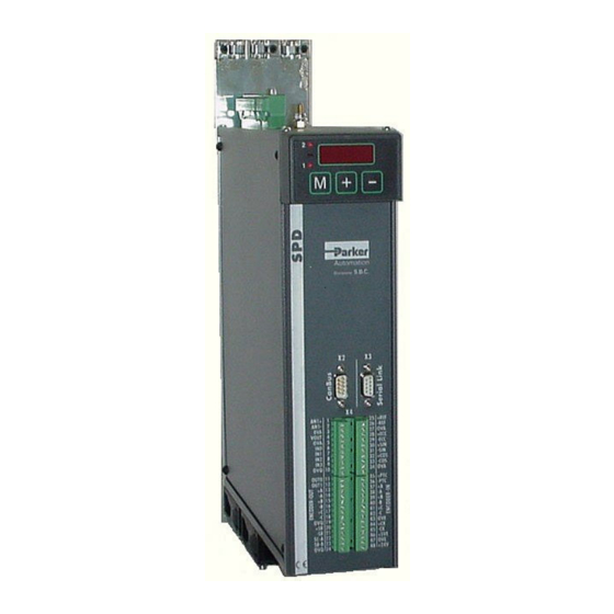
SPD
(2, 5, 8, 16, 24)
USER'S
MANUAL
Rev. 2.7
June 2005
(software rel. 12)
Table of
Contents
Previous
Page
Next
Page
1
2
3
4
5
Advertisement
Table of Contents
Need help?
Do you have a question about the SPD 2 and is the answer not in the manual?
Ask a question
Questions and answers
Related Manuals for Parker SPD 2
Industrial Equipment Parker SciLog FilterTec Plus Installation, Operation & Maintenance Instructions Manual
(72 pages)
Industrial Equipment Parker SCFT 02-02 Series Manual
(244 pages)
Industrial Equipment Parker SC80 Operator's Manual
Smart cycle / cold trap refrigerated air dryers (39 pages)
Industrial Equipment Parker SMOGHOG SHM-05C Owner's Manual
Media mist collector (36 pages)
Industrial Equipment Parker Finite JDK5000V Installation, Operating And Maintenance Manual
High pressure drain kits (2 pages)
Industrial Equipment Parker SAT Series Service Manual
Single acting hydraulic telescopic cylinder (24 pages)
Industrial Equipment Parker SPD 8 User Manual
(110 pages)
Industrial Equipment Parker SPD 16 User Manual
(110 pages)
Industrial Equipment Parker Siemens APOGEE P1 Manual
(20 pages)
Industrial Equipment Parker KarryFlare Operating Manual
Portable flaring device for triple-lok fittings (13 pages)
Industrial Equipment Parker ORIGA P120 Series Assembly Instructions Manual
(20 pages)
Industrial Equipment Parker P1F Manual
Pneumatic cylinders (32 pages)
Industrial Equipment Parker HTG Series Service Procedure
Integrated hydrostatic transmission (64 pages)
Industrial Equipment Parker VMS-3 Installation Operation & Maintenance
Ultraviolet systems (11 pages)
Industrial Equipment Parker Helac PowerTilt Series Service And Repair Manual
(60 pages)
Industrial Equipment Parker V14 Series Spare Parts Manual
(40 pages)
This manual is also suitable for:
Spd 5
Spd 8
Spd 16
Spd 24
Table of Contents
Print
Rename the bookmark
Delete bookmark?
Delete from my manuals?
Login
Sign In
OR
Sign in with Facebook
Sign in with Google
Upload manual
Upload from disk
Upload from URL


Need help?
Do you have a question about the SPD 2 and is the answer not in the manual?
Questions and answers