Table of Contents
Advertisement
Advertisement
Table of Contents

Subscribe to Our Youtube Channel
Related Manuals for Parker SciLog FilterTec Plus


Summary of Contents for Parker SciLog FilterTec Plus
- Page 1 ® ® SciLog FilterTec Plus Installation, Operation & Maintenance Instructions...
- Page 2 Parker Hannifin Corporation. Parker has a continuous policy of product development and although the Company reserves the right to change specification, it attempts to keep customers informed of any alterations. This publication is for general information only and customers are requested to contact our Process Filtration Sales Department for detailed information and advice on a product’s...
-
Page 3: Precautions
ALWAYS DISCONNECT this equipment from the power source before cleaning or performing maintenance. CALL Parker for parts, information and service. IF power cord is lost or damaged, contact Customer Service to obtain a new one. Do not replace it on your own. - Page 4 DÉBRANCHEZ TOUJOURS cet équipement de la source de courant avant de nettoyer ou d’exécuter l’entretien. APPELEZ PARKER pour pièces détachées, renseignements et entretien. SI le cordon d'alimentation est perdu ou endommagé, contactez le service clientèle pour en obtenir un nouveau. Ne le remplacez pas par vous-même.
-
Page 5: Table Of Contents
Table of Contents Precautions ........................3 Standards: ........................7 Installation & Start-Up: ....................7 Maintenance & Cleaning: ....................7 Introduction: ........................7 FilterTec Plus Maintenance ..................7 FilterTec Plus System Specifications: ................. 9 Installation of the USB Driver: ................... 11 Part A: FilterTec Plus Hardware ................. - Page 6 5.8 Setup: Pump ..................... 54 6.0 Manual: ........................56 7.0 Data Acquisition: ..................... 56 7.1 FilterTec Plus SciDoc Data Collection Software: ..........57 7.2 PC HyperTerminal Settings: ................61 Appendix “A” Application Examples ................62 FilterTec Plus Settings and Parameters Worksheets ..........65 ...
-
Page 7: Standards
Standards: EN 61326-1:2006, Class B EN 6100-3-2:2006 EN 6100-3-3:1995 +A1:2001 +A2:2006 EN 61010-1:2010 Ed.3+ C1;C2 Conforms to UL STD 61010-1:2012 Ed.3+R:29Apr2016 Certified to: CAN/CSA-C22.2 No 61010-1-12:2012 Ed.3+U1:U2 Installation & Start-Up: Installation of the FilterTec Plus™ System must be carried out only by trained personnel in accordance with the relevant regulations and this operations manual. - Page 8 +1 805 604 3401 email: bioscience.emea@parker.com email: bioscience.na@parker.com www.parker.com/bioprocessing www.parker.com/bioprocessing Parker customer service personnel will be able to serve you more efficiently if you have the following information: Serial number and model name of the equipment Installation procedure being used ...
-
Page 9: Filtertec Plus System Specifications
Pressure Range: The default pressure range of the sensors is 0-60psi, and is calibrated at the factory. Most peristaltic pumps generate pressures up to 40 psi. If you have need for higher pressures, contact Parker Customer Service for assistance. Electrical ... - Page 10 FilterTec Plus Balance Balances with capacity of 8,100 grams x 0.1 g resolution with all FilterTec Plus models. Larger balances available upon request. Contact Parker Customer Service. FilterTec Plus Software Main menu with five operational modes: Constant Rate Mode: Pumps at a user defined rate, and can switch to a user defined pressure with five, user-definable alarms, in particular, the Pmaintain Alarm that switches from Rate to Pressure control.
-
Page 11: Installation Of The Usb Driver
Installation of the USB Driver: Upon connecting the FilterTec Plus to the PC via a USB cable, the following “New Hardware Wizard” window appears. Select ‘No, not at this time” and click “Next”. The second screen appears: Insert the CD containing the FilterTec Plus Operating Manual into the PC, choose “Install the software automatically”... - Page 12 Windows 7 users will often not have the “New Hardware Wizard” run properly, and the driver will not be installed. When this occurs: Open Device Manager and look under Other Devices for “Unknown Device” or similar and double-click on that device. Click on “Update Driver”...
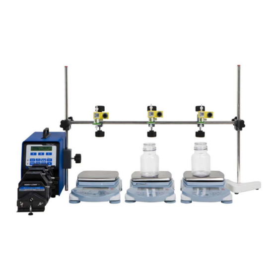
- Page 13 FilterTec Plus Quick Start: The FilterTec Plus is shipped in conjunction with a 3-Filter Testing Station. This Station consists of 3 balances with cables, the Serial3 Balance Interface box, and a stand and clamp set for holding your 3 filters over the balances. A 6-way Rotary Valve may also be purchased with this system and its actions implemented in the Programmable R-P Mode.
- Page 14 11. Press Exec and Run when ready to start the process and begin data collection. 12. Please refer to the FilterTec manual for descriptions of the parameters and modes. 13. Parker strongly recommends testing and calibration of the system with distilled water or a surrogate solution prior to running your process fluids.
-
Page 15: Part A: Filtertec Plus Hardware
Alternatively, any alarm can be selectively disabled. All pump filtration, as well as alarm parameters can be printed out at user defined time intervals with a Parker serial printer. Alternatively, all of the collected data can be sent to a supervisory computer for data archiving using SciDoc or HyperTerminal. -
Page 16: Front Panel: Data Entry & Display
2.0 Front Panel: Data Entry & Display The front panel consists of a user interface, which includes an alphanumeric display and a membrane keypad to select operational modes and alarm settings. The display is a two line, 20 characters each, liquid crystal display (LCD). The display is backlit to allow easy viewing over a wide range of lighting conditions. -
Page 17: Back Panel: Interface Options
Printer Port: The FilterTec Plus can be connected to a PC for data collection or to a Printer via the female DB9 RS-232 port labeled “Printer”. You need a Parker RS-232 cable (P/N 080-073) to connect to a PC for data archival, or a printer cable (080-096) to make the connection between the printer and the FilterTec Plus. - Page 18 Mettler: PGS, PM, Viper Models P/N: 080-067PGS Ohaus: GT, “Precision Advanced” P/N: 080-066 & “Explorer” & “Voyager” Models Ohaus: IP Series High Capacity P/N: 080-067 Ohaus: Adventurer Pro Series P/N: 080-067PGS Sartorius: Most Series Balances P/N: 080-068 ...
- Page 19 4-20 ma Analog inputs (A1, A2 & A3) for recording data or alarming based upon that data. It also allows an interface with Parker foot switch (P/N: 080-059) and allows remote Start / Stop control of the FilterTec Plus.
-
Page 20: Pressure Sensor Installation
The SciPres Disposable pressure sensors are easy to change when the need arises, and are readily available from Parker in packs of 5. They may be sanitized using several methods, CIP with NaOH or alcohol, autoclaved up to twice, or gamma irradiated. (Only those with grey rings... -
Page 21: Part B: Filtertec Plus Software
Part B: FilterTec Plus Software 1.0 MAIN MENU SELECT EDIT SELECT Mode CONSTANT RATE Const. RATE MODE - SETUP - PUMP TUBING PUMP TUBING: DOWN SELECT EXEC EDIT PRIME DOWN SELECT DOWN SELECT SELECT SELECT SELECT Mode Select SETUP - SETUP - SCALE - SCALE - SCALE MANUF. -
Page 22: Software Overview: Main Menu
1.0 Software Overview: Main Menu The FilterTec Plus main menu consists of five (5) operational modes as shown on the previous page. Use the “Up” and “Down” keys to scroll through the main menu. Press the “Select” key to enter a chosen operational mode, i.e. CONSTANT RATE. Pressing the “Select” key enters the 1 submenu level, which provides access to the “Exec”, “Edit”, and “Prime”... - Page 23 manner. This is accomplished by entering step-by-step instructions from the FilterTec Plus front panel buttons. You can enter and control by using Run, Stop, Time, Direction, R-Step, R-Scan, P-Step, P-Scan, V, and W commands to have the system perform changing rates and pressures, even rotary selector valve positions for switching buffers or collection vessels.
- Page 24 2.0 CONSTANT RATE MODE Constant Rate / Constant Pressure Filtration: Edit Menu Mode CONSTANT RATE DOWN SELECT SELECT Const. RATE MODE EXEC EDIT PRIME EDIT SELECT - SETUP - PUMP TUBING PUMP TUBING: DOWN SELECT DOWN SELECT DOWN SELECT - SETUP – RESPONSE F. RESPONSE FACTOR: 100 DOWN SELECT...
-
Page 25: Constant Rate Mode: Constant Rate/Pressure Filtration
P1, P2 and P3. The FilterTec Plus must not be running when resetting pressure sensor output, and the sensor must be plugged in. Do not use the SPAN key unless instructed to do so by Parker Customer Service. This is used to calibrate the pressure sensor output, and requires additional hardware. - Page 26 Hi and Lo-Pressure alarms are related to the Pressure Source chosen in SETUP: Press. Sensor, Source. The Alarm condition is triggered when alarm limit is exceeded. Alarms are not mutually exclusive. You may select any combination of alarms. Pump Rate: Select pump rate in terms of ml/min, however first select pump tube size, see 2.1. Pump Rate may be changed “on the fly”...
-
Page 27: Pump Re-Calibration
2.1 Pump Re-calibration: The FilterTec Plus contains a permanent calibration table for each of the nine (9) tubing sizes: 13, 14, 16, 25, 17, 15, 24 & 35. For a given pump tube size, the calibration table relates the pump motor RPM with the pump output in terms of ml / min. However, the user can update the FilterTec Plus pump calibration very easily. -
Page 28: Constant Rate Mode: Alarm Limits
2.2 CONSTANT RATE MODE Constant Rate / Constant Pressure Filtration: Alarm Limits Menu - SETUP - ALARM LIMITS DOWN SELECT SELECT SELECT LIMIT: CUMUL VOLUME CUMUL VOL: 1000 DOWN SELECT DOWN SELECT DOWN SELECT LIMIT: LO-FLOW LO FLOW: 0 ml/m DOWN SELECT DOWN... - Page 29 2.2 CONSTANT RATE Mode: Alarm Limits SUMMARY: This section allows the assignment of limiting values for several alarm conditions: Cumulative Volume (CV) (based on feed rate) in ml; Lo-Flow (LC) (based upon collection rate in ml/min; Hi-Temp (HT) in ⁰C; Run Time (RT) in Hours: Minutes; Lo-Pressure (LP) (monitor system leakage) in psi;...
- Page 30 100.0 300.0 Press RUN to Finish "DisplaySwitch" "EXIT" 30.0 30.0 CONSTANT RATE 30.0 90.0 Exec Edit Prime 2.3 Constant Rate: Const. Rate / Const. Pressure Filtration; Execute Display Mode CONSTANT RATE The "Display/Switch" key on the front panel allows you to change between 3 operational display screens.
- Page 31 3.0 CONSTANT PRESSURE MODE Constant Pressure Filtration: Edit Menu Mode CONST. PRESSURE DOWN SELECT SELECT Const. PRESSURE MODE EXEC EDIT PRIME EDIT SELECT - SETUP - PUMP TUBING PUMP TUBING: DOWN SELECT DOWN SELECT DOWN SELECT - SETUP – RESPONSE F. RESPONSE FACTOR: 100 DOWN SELECT...
-
Page 32: Constant Pressure: Constant Pressure Filtration
3.0 CONSTANT PRESSURE: Constant Pressure Filtration SUMMARY: This FilterTec Plus mode allows implementation of a constant pressure filtration, i.e. a user selected filter backpressure is achieved and maintained throughout the filtration process. When the filter device starts plugging up, the FilterTec Plus detects a corresponding increase in filter backpressure. - Page 33 3.1 CONSTANT PRESSURE MODE Constant Pressure Filtration: Alarm Limits Menu - SETUP - ALARM LIMITS DOWN SELECT SELECT SELECT LIMIT: CUMUL VOLUME CUMUL VOL: 1000 DOWN SELECT DOWN SELECT DOWN SELECT LIMIT: HI-TEMP TEMP LIMIT: 35.0 DOWN SELECT Incr. Decr. SELECT DOWN SELECT...
-
Page 34: Constant Pressure: Alarm Limits
3.1 CONSTANT PRESSURE: Alarm Limits SUMMARY: This section allows you to assign limiting values for several different alarm conditions: Cumulative Volume (CV) in milliliters; Hi Temperature in ⁰C; Run Time (RT) in Hours: Minutes; Lo-Pressure (LP) (monitor system leakage) in psi; Lo-Flow (LC) (pump will stop when collection rate falls below this limit) in ml/min.;... - Page 35 Constant Pressure: Constant Pressure Filtration: Execute Display Mode CONST. PRESSURE The "Display/Switch" key on the front panel allows you Down Select to change between 3 operational display screens. Abbreviations are as follows: Select P1= Pressure @ P1 CONSTANT PRESSURE P2= Pressure @ P2 Exec Edit Prime...
- Page 36 4.0 Programmable R-P: Programmed Variable Rate/Pressure Filtration Mode PROGRAMMABLE RP Down Select Exit Select PROGRAMMABLE R-P Exec Edit Setup Edit START Next Delete Last Rate Pressure RATE PRESS. Press Next Delete Last Select Exit Select "CW" "Rate" Select R-Step: R-Scan: Press Next Delete...
-
Page 37: Programmable R-P: How To Generate A Programmable R-P Program
4.0 PROGRAMMABLE R-P: How to generate a PROGRAMMABLE R-P program. SUMMARY: In PROGRAMMABLE R-P Mode you can generate a program that changes flow rates or controlled pressure rates in a stair-stepped (STEP) or ramped (SCAN) manner over time. If you wish, you can also control a pair of rotary selector valves, or repeat the program automatically. - Page 38 Optional Commands: Vx, Wx, Valve Position: This program statement is implemented by pressing the star (*) key followed by selecting “Rotary Valve”. Six rotary valve positions for valve “V”, namely, V1 thru V6, as well as, six rotary positions for a second valve “W”, W1 through W6, can be selected. COUNT : Allows you to repeat the program automatically, and not generally used.
-
Page 40: Programmable R-P: Setup
4.1 PROGRAMMABLE R-P: Setup SUMMARY: The Setup menu is identical to the Edit menus in the other two modes except that the Pump Rate and Pump Pressure are input as part of the Step-by-Step instructions mentioned in the previous section. Use “Up”... - Page 41 4.2 PROGAMMABLE R-P MODE: Alarm Limits Menu - SETUP - ALARM LIMITS DOWN SELECT SELECT SELECT LIMIT: CUMUL VOLUME CUMUL VOL: 1000 DOWN SELECT DOWN SELECT DOWN SELECT LIMIT: HI-TEMP TEMP LIMIT: 35.0 DOWN SELECT Incr. Decr. SELECT DOWN SELECT LIMIT: RUN TIME RUN TIME: 01:00...
-
Page 42: Programmable R-P: Alarm Limits
4.2 PROGRAMMABLE R-P: Alarm Limits SUMMARY: This section describes assigning limiting values for several alarm conditions: Cumulative Volume in milliliters; Hi-Temperature in ⁰C; Lo-Pressure (monitor system leakage) in psi; Hi-Pressure (Monitor filter plug-up) in psi; Lo-Flow (pump will stop when pump feed rate falls below this limit) in ml/min.;... - Page 43 5.0 SETUP MODE SELECT SETUP DOWN SELECT SELECT SELECT - SETUP - SCALE - SCALE- SCALE MANF. SCALE MANF: OHAUS3 DOWN SELECT DOWN SELECT DOWN SELECT DOWN SELECT - SETUP - CLOCK - CLOCK- TIME OF DAY TIME: 12:00 DOWN SELECT DOWN SELECT...
-
Page 44: Setup
Units : Choose from Psi (default), Bar, or Kpa. Range: Default is 60, can be set lower, will require re-calibration of the input. Contact Parker Customer Service for assistance.. Pump: Select the following user preferences: Keypad Beep: (On/Off), Switch Configuration: (Level / Pulse), Switch Polarity: (Normal/Inverted), TTL1:On-Off: (Yes/No), Set Yes if controlling another pump as a slave, set NO if controlling Rotary Selector Valve “W”. -
Page 45: Setup: Scale
5.1 Setup: Scale - SETUP - SCALE DOWN SELECT SELECT - SCALE- SCALE MANF. SCALE MANF: OHAUS3 DOWN SELECT DOWN SELECT DOWN - SCALE- ALARM ALARM: PUMP STOP DOWN SELECT DOWN SELECT DOWN - SCALE- TARE WEIGHT TARE WEIGHT: OFF DOWN SELECT DOWN... -
Page 46: Ohaus Adventurer Pro Balance Parameters
An Ohaus Adventurer Pro AV8101 scale is normally sent with the system when purchased. If a different scale is required, please contact Parker Technical Support for configuration information. 5.11 Ohaus Adventurer Pro Balance Parameters: Press and hold the Menu button until MENU appears on the display. Release this button, and now use the Yes, No, and Back buttons to navigate the Sub-menus. -
Page 47: Setup: Clock
5.2 Setup: Clock - SETUP - CLOCK DOWN SELECT SELECT - CLOCK- TIME OF DAY TIME: 12:00 DOWN SELECT INCR DECR SELECT DOWN - CLOCK- PRINT ENABLE PRINT: TIME OF DAY DOWN SELECT INCR DECR SELECT DOWN - CLOCK- YEAR YEAR: 2009 DOWN... -
Page 48: Setup: Test Mode
5.3 Setup: Test Mode: - SETUP – TEST MODE DOWN SELECT SELECT SCALE INTITIALIZATION SCALE ERROR Please Wait Hit any key STAR KEY STAR KEY - TEST- 10% 00000 - TEST- PRESSURE - TEST- ANALOG 00.0 00.0 00.0 STAR KEY STAR KEY STAR KEY - TEST- KEYPAD... -
Page 49: Setup: Ethernet
5.4 Setup: Ethernet - SETUP - ETHERNET DOWN SELECT SELECT ETHERNET: ADDR1 ETHERNET ADDR1: 192 ETHERNET: MASK3 ETHERNET MASK3: 255 DOWN SELECT INCR DECR SELECT DOWN SELECT INCR DECR SELECT ETHERNET: ADDR2 ETHERNET ADDR1: 168 ETHERNET: MASK4 ETHERNET MASK4: DOWN SELECT INCR DECR... -
Page 50: Setup: Printer
DOWN SELECT Printer allows the setting of RS-232 communication parameters needed for connection to a Parker serial printer or to a PC for data collection. Print Time: Controls how fast the FilterTec Plus sends data points in Minutes: Seconds. -
Page 51: Setup: Analog
5.6 Setup: Analog - SETUP - ANALOG DOWN SELECT SELECT ANALOG: LOW RANGE 1 LO ANALOG1: ANALOG: LOW RANGE 2 LO ANALOG1: ANALOG: LOW RANGE 3 LO ANALOG3: DOWN SELECT INCR DECR SELECT DOWN SELECT INCR DECR SELECT DOWN SELECT INCR DECR SELECT... -
Page 52: Setup: Pressure Sensor
5.7 Setup: Pressure Sensor - SETUP-PRESS.SENSOR DOWN SELECT SELECT PRESSURE: RANGE PRESS RANGE: 60.0 DOWN SELECT DOWN SELECT DOWN PRESSURE: UNITS PRESSURE UNITS: PSI DOWN SELECT DOWN SELECT DOWN PRESSURE: SOURCE PRESS SOURCE: DOWN SELECT DOWN SELECT DOWN PRESSURE: ZERO PRESSURE: ZERO PRESSURE: 1... -
Page 53: Setup: Pressure Sensor, Calibration
5.7 Setup: Pressure Sensor, Calibration The FilterTec Plus has built in calibration curves for the SciPres disposable pressure sensors that are inherently very accurate for the installed default range of 0 – 60 psi, and there should be no need for you to change it. If your metrology department insists that they calibrate them periodically, the procedure follows. -
Page 54: Setup: Pump
5.8 Setup: Pump - SETUP - PUMP DOWN SELECT - PUMP – KEYPAD BEEP KEY BEEP: DOWN SELECT DOWN SELECT -PUMP- FACTORY RESET CLEAR ALL MEMORY? ARE YOU SURE? DOWN SELECT EXIT EXIT - PUMP - ASCII FEEDB ASCII FEEDBACK: DOWN SELECT DOWN... - Page 55 5.8 Setup: Pump, continued: Setup: Pump provides configuration of global settings related to the pump. Generally, the default values here do not need to be changed. Any changes required for a particular system will be made at the factory, and would only need to be modified if a “Factory Reset” is performed.
-
Page 56: Manual
When a PC is connected, all data generated in RATE, PRESSURE, and STEP-SCAN modes can be sent to the PC for archiving. Please use the Parker SciDoc Data Collection Software described below. Alternatively, a PC running “HyperTerminal”, a program that comes with Windows, may be used to capture the data. -
Page 57: Filtertec Plus Scidoc Data Collection Software
It consists of a copy of WinWedge32 from TalTech Inc. and a custom spreadsheet with built in macros. It requires the use of a Parker RS-232 cable, (P/N: 080-073) or USB cable, (P/N: 090-158) to connect your FilterTec Plus to an available Com Port on your PC. - Page 58 Here the data sheet is setup for the mode being used and the number of pressure sensors in use. As this spreadsheet is also used for the FilterTec, options for one, two or three balances exist. Setting it for less than three will not affect the data received; there may be columns of data that are hidden.
- Page 59 After pressing OK, the empty datasheet appears: When ready, press EXEC on the FilterTec Plus, and then RUN after the balance has initialized. The data generated will automatically be placed in the cells of the spreadsheet, and the charts populated with the same data. The text box in the upper left of the spreadsheet contains the header information that is generated by the FilterTec Plus.
- Page 60 “Select” button on the front panel to finalize the choice. As the process is continuing while this is done, the data will reflect the change. Please contact Parker customer service at 805-604-3400 or Technical Support at 608-824-0500 if you have any questions, comments or suggestions regarding the use of this data collection...
-
Page 61: Pc Hyperterminal Settings
7.2 PC HyperTerminal Settings: FilterTec Plus to PC: For PC Connections via the Printer Port a Parker RS-232 Cable (P/N: 080-073) is needed. When not using the Parker printer, this allows process data to be “dumped” into a PC for archiving. The list of settings below must match those in Setup: Printer of the FilterTec Plus, and Print Delay should be set to “0”. -
Page 62: Appendix "A" Application Examples
Appendix “A” Application Examples... - Page 63 The FilterTec Plus allows filter capacity determinations to be are carried out by the following methods: Constant Pump Rate Constant Pressure, V Constant Pump Rate followed Programmable Step/Scan Rate/Pressure by Constant Pressure The data obtained from these methods is used to determine optimal filtration conditions to process a given volume of solution by dead-end filtration.
- Page 64 The following diagrams show the various configurations of the FilterTec Plus system. This is the most common setup, using a single filter and pressure sensor. This is the other common setup, for testing a filter-train, using 3 filters and 3 sensors in series. These may be augmented by use of a 6-way Rotary Valve to change from one solution to another in a programmed manner, using the Programmable R-P Mode.
-
Page 65: Filtertec Plus Settings And Parameters Worksheets
FilterTec Plus Settings and Parameters Worksheets F ilter P ro g r am m a b le R -P M o d e F ilte r C a r tr idg e P u m p Tu b in g F ilte r A re a , s q M R e s p on s e F ac to r M a n ufa c tu r er... -
Page 66: Appendix B: Troubleshooting
Appendix B: Troubleshooting... -
Page 67: Peristaltic Pump Heads
Check the following: Possible Solution Does “Check Pump Head” If it occurs with no tubing in the occur with no tubing in the head, call Parker. You may head? need a new motor. When “Check Pump Head” error occurs with your If no, make sure you are using peristaltic head. - Page 68 Ok, the scale is chosen check the scale settings, or call correctly, and it still doesn’t Parker tech support for help work. Now what? correcting them if you are not using the default scale. If someone other than yourself...
-
Page 69: Piston And Magnetic Gear Heads
If it still won’t turn, contact Are you pumping a gritty Parker to arrange an RGA to solution, or one that can send your pump in for service, crystallize if allowed to dry or purchasing a service kit if you out? have a magnetic gear head. -
Page 70: Scidoc Documentation Software
C. SciDoc Documentation Software When this occurs: Check the following: Possible Solution Check Device Manager from the properties page of the My Computer Icon. Expand the + next to Ports, Com and LPT. What Com ports exist, and are they functioning properly? If all in Device Mgr is fine, then some other program is using the Com Port, consult your IT or MIS... -
Page 71: Filtertec Plus Specific Issues
D. FilterTec Plus Specific issues When this occurs: Check the following: Possible Solution Review suggestions for the Is it connected and “Scale Error” problem listed configured correctly? above. If your not getting this error, see #2 that follows. If the Filtrate Weight Alarm under Alarm Enable: Filtrate Wgt. - Page 72 Parker Hannifin Corporation Parker Hannifin Corporation © 2015 Parker Hannifin Corporation. All rights reserved. Bioscience Division – N.A. Bioscience Division – N.A. 2340 Eastman Avenue 2340 Eastman Avenue IOMI-AK2-005_RevB Oxnard, California, USA 93030 Oxnard, California, USA 93030 toll free: 877 784 2234...
Need help?
Do you have a question about the SciLog FilterTec Plus and is the answer not in the manual?
Questions and answers