
Related Manuals for Speco O2P20X


Summary of Contents for Speco O2P20X
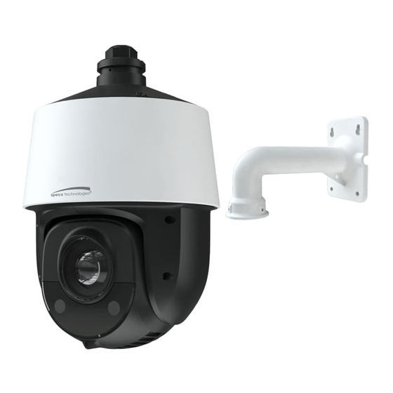
- Page 1 User Manual PTZ Network Camera O2P20X Please read this instruction carefully before operating the unit and keep it for further reference...
- Page 2 1. Electrical safety All installation and operation here should conform to local electrical safety codes. Use a certified/listed 12VDC/DC24V/AC24V power supply only. Please note: Do not connect two power supplying sources to the device at the same time; it may result in device damage! The product must be grounded to reduce the risk of electric shock.
- Page 3 Statement This guide is for reference only. Product, manuals, and specifications may be modified without prior notice. Speco Technologies reserves the right to modify these without notice and without incurring any obligation. Speco Technologies is not liable for any loss caused by improper operation.
-
Page 4: Table Of Contents
Table of Contents Introduction ..........................................2 Web Access and Login ......................................3 Live View..........................................4 PTZ Menu Setup ........................................6 System Information................................6 System Setup ..................................6 4.2.1 Auto PT Flip ................................. 7 4.2.2 Language Setup................................7 4.2.3 Date Setup .................................. 7 4.2.4 Title Setup ................................... - Page 5 5.4.3 Alarm Server ................................25 Analytics Configuration ..............................26 5.5.1 Object Removal .................................26 5.5.2 Exception ..................................27 5.5.3 Line Crossing ................................28 5.5.4 Intrusion ..................................29 5.5.5 Crowd Density ................................30 5.5.6 People Intrusion ................................32 5.5.7 People Counting ................................33 5.5.8 Face Detection ................................34 Network Configuration ..............................35 5.6.1 TCP/IP ..................................35 5.6.2...
-
Page 6: Introduction
Thank you for purchasing this network camera! Please read this manual carefully before operating the unit and retain it for further reference. Should you require any technical assistance, please contact Speco Technologies Technical Support at 1-800-645-5516. Main Features Built-in PoE (Power over Ethernet) ... -
Page 7: Web Access And Login
2 Web Access and Login The IP camera settings can be accessed via a web browser (Internet Explorer 8 and up) through the LAN. Access through IP Scanner Network connection: ①Make sure the PC and IP-Cam are connected on the same local network. The camera is set to DHCP by default and will be assigned an IP address by the DHCP server. -
Page 8: Live View
3 Live View The window below will be shown after logging in. The following table describes the icons on the live view interface. Icon Description Icon Description Original size Color abnormal indicator Fit correct scale Abnormal clarity indicator Auto (fill the window) Scene change indicator Full screen Line crossing indicator... - Page 9 Click the PTZ icon to reveal the PTZ control panel. The descriptions of the control panel are as follows: Icon Description Icon Description Move upper left direction Move upper right direction Move up Stop movement Move left Move right Move lower left direction Move lower right direction Move down Speed adjustment...
-
Page 10: Ptz Menu Setup
4 PTZ Menu Setup On the PTZ control panel of IE remote preview interface, call Preset 95 and click . This will take you to see the following main menu setup. The menu setup can be displayed when the resolution of the live is set to 1920×1080. After you go to the main menu interface, you can select the menu by clicking the direction button ( :To select menu by moving up and down. -
Page 11: Auto Pt Flip
4.2.1 Auto PT Flip Select Auto PT Flip and then click to set up the menu on the right; click button to select On/Off. If “On” is selected, please click button to return to the menu on the left and click button to select Exit. -
Page 12: New Password And Change Password
4.2.6 New Password and Change Password New Password Enter the password by clicking button. Numbers from 0 to 9 are available. The password should be 6 characters. Empty password is invalid when you set the new password. Password needs to be entered when you log in next time. -
Page 13: Image Setup
【Brightness】: Set the brightness level of the camera’s image. 【Sharpness】: Set the resolution level of the image plane and the sharpness level of the image edge. 【Contrast】: Set the color difference between the brightest and darkest parts. 【Hue】: Set the total color degree of the image. 【Antiflicker】: Off: disables the anti-flicker function. - Page 14 AE Setup Go to AE Setup menu as shown below: 【AE MODE】: Auto, Bright, Shutter, IRIS and Manual are optional. 【Brightness】 : Range from 0(darkest)~20(brightness). It is available only when bright mode is selected. 【Shutter】 :The lower the value of camera shutter is, the brighter the image is. It is available only when the shutter or manual mode is selected.
-
Page 15: Lens Setup
4.3.3 Lens Setup Go to Camera SetupLens Setup menu as shown below: Focus Limit Set the nearest distance of focus. Options: 1m, 1.5m, 2m, 3m, 5m and 10m. Zoom MAG DISP If “ON” is selected, you will see the zoom magnification in the live image ... -
Page 16: Infrared Control
4.3.5 Infrared Control Auto, ON or OFF is optional. 4.3.6 Video Format PAL or NTSC is optional. 4.3.7 Smart IR Setup Smart IR Mode: “Auto”, “Manual” or “OFF”. This function can effectively avoid image overexposure and underexposure by controlling the brightness of the IR lights according to the actual conditions to make the image more realistic. Please enable and set it as needed. -
Page 17: Cruise Setup
4.4.2 Cruise Setup Go to Dome FunctionCruise Setup menu as below: In this interface, by programming presets in cruise list in advance, the system will keep calling those presets at the set time in sequence when executing cruise command so that non-stop monitoring between multiple important positions can be achieved. Setting steps are as follows: ①... -
Page 18: Task Setup
4.4.4 Task Setup Go to Dome FunctionTask Setup menu as shown below: By dividing 24 hours into several periods and appointing different commands for each period, the camera system will automatically execute the commands according to the set time if there is no operation. Setting Steps: ①... -
Page 19: Alarm Setup
4.4.6 Alarm Setup Go to Dome FunctionAlarm Setup as shown below: Setting Steps: ① Select Alarm In No. ② Go to “EDIT CUR ALARM IN” menu as shown below. 【ALARM IN CON】:Set the alarm enter type to be Normally Opened (N.O.) or Normally Closed (N.C.) according to the sensor type. 【ALARM IN MODE】:ON, OFF and TIME are optional. -
Page 20: Load Default
4.6 Load Default There are three menus, including master reset, master clear and system reboot. 【Master Reset】 : Restore the camera state and active menu to the factory default settings but do not clear those parameters such as preset, cruise. 【Master Clear】... -
Page 21: System Configuration
5.1 System Configuration 5.1.1 System Information In the “System Information” interface, the system information of the device is listed. 5.1.2 Date and Time To set the time and date, go to SystemDate and Time. Please refer to the following interface. Select the applicable time zone and enable / disable DST as needed. - Page 22 SD Card Management When the card is used for the first time, click the “Format” button to format the SD card. All data on the card will be cleared by clicking this button. Click the “Eject” button to stop writing data to the SD card. Then the SD card can be ejected safely. Snapshot Quota: Set the capacity proportion of captured pictures on the SD card.
- Page 23 Weekly schedule Set the alarm time from Monday to Sunday for a single week. Each day is divided in one hour increments. Green means scheduled. Blank means unscheduled. “Add”: Add the schedule for a special day. Drag the mouse to set the time on the timeline. “Erase”: Delete the schedule.
-
Page 24: Video Configuration
snapshots is less than the set quantity of snapshots. Timing Snapshot: Enable timing snapshot first and then set the snapshot interval and schedule. The setup steps of schedule are the same as the schedule recording (See Schedule Recording). 5.2 Video Configuration Video Configuration includes Image Settings, Video/Audio Setup, OSD, Privacy Mask and Region of Interest. -
Page 25: Video / Audio Configuration
Drag “ ” icons to set the time of day and night. Blue means day time and blank means night time. If the current mode of camera parameters is set to “Timing”, the image configuration mode will automatically switch between day and night according to the schedule. -
Page 26: Osd Configuration
5.2.3 OSD Configuration Go to VideoOSD interface as shown below. Set time stamp, device name, OSD content and picture overlap here. After enabling the corresponding display and entering the content, drag them to change their position. Then click the “Save” button to save the settings. Show Azimuth: Show the PTZ moving direction on the live view interface. -
Page 27: Ptz Configuration
1. Enable video mask. 2. Click direction buttons to change the area you want to mask. 3. Click “Draw Area” and then drag the mouse to draw the video mask area. 4. Click “Add” to add the mask area. 5. Return to the live to verify that the area have been drawn as shown as blocked out in the image. To clear the video mask: Select the mask area in the mask area list and then click the “Delete”... -
Page 28: Ptz Function
5.3.3 PTZ Function PTZ function includes preset setup, cruise setup, group setup, trace setup, task setup, alarm setup, home position setup and wiper setup. Please refer to Chapter 4.4 Dome Function for more details. 5.4 Alarm Setup 5.4.1 Motion Detection Go to Alarm SetupMotion Detection to set motion detection alarm. -
Page 29: Other Alarms
motion detection area. After that, click the “Save” to save the settings. “Clear All” can be used to clear out the entire motion zone. 3. Set the schedule for motion detection. The schedule setup steps of the motion detection are the same as the schedule recording setup (See Schedule Recording). -
Page 30: Analytics Configuration
5.5 Analytics Configuration This series of IP cameras supports certain smart functions, such as line crossing detection, region intrusion detection, etc. These events can be triggered as alarm events. For more accuracy, here are some recommendations for installation. Cameras should be installed on stable surfaces, as vibrations can affect the accuracy of detection. ... -
Page 31: Exception
4. Set the alarm area number and then enter the desired alarm area name. Up to 4 alarm areas can be added. Click the “Draw Area” button and then click around the area where you want to set as the alarm area in the image (the alarm area should be a closed area). Click the “Stop Draw”... -
Page 32: Line Crossing
detection chapter for details. 3. Click “Save” to save the settings. 4. Set the sensitivity of the exception detection. Click “Sensitivity” tab to go to the interface as shown below. Drag the slider to set the sensitivity value or directly enter the sensitivity value in the textbox. Click “Save” to save the settings. The sensitivity value of Scene Change Detection: The higher the value is, the more sensitive the system responds to the amplitude of the scene change. -
Page 33: Intrusion
Set the alarm line number and direction. Up to 4 lines can be added. Multiple lines cannot be added simultaneously. Direction:A<->B, A->B and A<-B optional. This indicates the direction of the intruder who crosses over the alarm line that would trigger the alarm. -
Page 34: Crowd Density
1. Enable intrusion alarm. 2. Set the alarm holding time and alarm trigger options. The setup steps are the same as motion detection. Please refer to motion detection chapter for details. 3. Click the “Save” button to save the settings. 4. - Page 35 Enable the crowd density detection. Set “Refresh Frequency”, “Density Alarm Threshold” and “Alarm Holding Time”. Refresh Frequency: The refresh frequency of the detection result. Density Alarm Threshold: Alarms will be triggered once the percentage of the crowd density in a specified area exceeds the pre-defined threshold value.
-
Page 36: People Intrusion
2. The size range of a single person image should take up from 1% to 5% of the entire image and the height range of a single person image should occupy from 1/5 to 1/2 of the entire image. 3. This function is inapplicable to the scene where there are many moving objects except human shape. (eg. moving cars) 4. -
Page 37: People Counting
5.5.7 People Counting This function is to calculate the number of the people entering or exiting from the detected area through detecting, tracking and counting the head shapes of the people. The setup steps are as follows. 1. Go to ConfigEventPeople Counting as shown below. Enable the people counting detection. -
Page 38: Face Detection
Click “Draw Area” and drag the mouse to draw a rectangle area. Drag the four border lines or the four corners of the rectangle to modify its size. Click “Stop Draw” to stop drawing the area. Click “Clear” to clear the area. Click and drag the arrow or the other end of the arrow line to change the people entrance direction. -
Page 39: Network Configuration
2. Enable the face detection function. Save Source Information: if checked, the whole picture will be saved to an SD card when detecting a face. Save Face Information: if checked, the captured face picture will be saved to an SD card when detecting a face. Note: To save images to a local PC, please enable “Save Face Snapshots”... -
Page 40: Port
Use IP address (take IPv4 for example)-obtain a local IP address automatically through DHCP. A typical router has a DHCP server built in, and therefore is able to assign an IP address to the camera. Use PPPoE-Click the “PPPoEConfig” tab to go to the interface as shown below. Enable PPPoE and then enter the user name and password from your ISP. -
Page 41: Server Configuration
HTTP Port: The default HTTP port is 80. It can be changed to any port which is not occupied. HTTPS Port: The default HTTPs port is 443. It can be changed to any port which is not occupied. Data Port: The default data port is 9008. Please change it as necessary. RTSP Port: The default port is 554. -
Page 42: Snmp
5.6.5 SNMP To get camera status, parameters and alarm information and remotely manage the camera, the SNMP function can be used. Before using SNMP, please install an SNMP management tool and set the parameters of the SNMP, such as SNMP port, trap address. 1. -
Page 43: 802.1X
5.6.6 802.1x If it is enabled, the camera’s data can be protected. When the camera is connected to the network protected by the IEE802.1x, user authentication is needed. To use this function, the camera shall be connected to a switch supporting 802.1x protocol. The switch can be reckoned as an authentication system to identify the device in a local network. -
Page 44: Upnp
5.6.8 UPNP If this function is enabled, the camera can be quickly accessed through the LAN. Go to NetworkUPnP. Enable UPNP and then enter UPnP name. 5.6.9 Email If you need to trigger Email when an alarm happens or IP address is changed, please set the Email here first. Go to NetworkEmail. -
Page 45: Https
Server Name: The name of the FTP server. Server Address: The IP address or domain name of the FTP. Upload Path: The directory where files will be uploaded to. Port: The port of the FTP server. Use Name and Password: The username and password that are used to login to the FTP server. 5.6.11 HTTPS HTTPs provides authentication of the web site and protects user privacy. -
Page 46: Qos
Click the “Create” button to create a private certificate. Enter the country (only two letters available), domain (camera’s IP address/domain), validity date, password, province/state, region and so on. Then click “OK” to save the settings. * Click “Create a certificate request” to enter the following interface. Click “Create”... - Page 47 Add user: 1. Click “Add” to pop up the following textbox. 2. Enter user name in “User Name” textbox. 3. Enter letters or numbers in “Password” and “Confirm Password” textbox. Please set the password according to the requirement of the password security level (Go to SetupSecuritySecurity ManagementPassword Security interface to set the security level). 4.
-
Page 48: Online User
3. Enter the old password of the user in the “Old Password” text box. 4. Enter the new password in the “New password” and “Confirm Password” text box. 5. Enter computer’s MAC address as necessary. 6. Click the “OK” button to save the settings. Note: To change the access level of a user, the user must be deleted and added again with the new access level. -
Page 49: Maintenance Configuration
enabled, login failure after trying six times will make the login interface locked. The camera can be logged in again after a half hour or after the camera reboots. Password Security Please set the password level and expiration time as needed. Password Level: Weak, Medium or Strong. -
Page 50: Reboot
5.8.2 Reboot Go to MaintenanceReboot. Click the “Reboot” button to reboot the device. Timed Reboot Setting: If necessary, the camera can be set up to reboot on a time interval. Enable “Time Settings”, set the date and time and then click the “Save”... -
Page 51: Search
6 Search 6.1 Image Search In the Setup interface, click Search to go to the interface as shown below. Images that are saved on the PC or SD card can be found here. Local Image Search 1. Choose “Picture”—“Local”. 2. - Page 52 Click to return to the previous interface. SD Card Image Search 1. Choose “Picture”—“SD Card”. 2. Set time: Select date and choose the start and end time. 3. Choose the alarm events at the bottom of the interface. 4. Click to search the images.
-
Page 53: Video Search
Icon Description Icon Description Close: Select an image and click Close all: Click this button to close all this button to close the image. images. Save: Click this button to select the Save all: Click this button to select the path for saving the image on the path for saving all pictures on the PC. -
Page 54: Sd Card Video Search
Icon Description Icon Description Play button. After pausing the video, Pause button click this button to continue playing. Stop button Speed down Speed up Watermark display Enable / disable audio; drag the slider to adjust the volume after enabling audio. 6.2.2 SD Card Video Search Click Search to go to the interface as shown below. - Page 55 4. Select the alarm events at the bottom of the interface. 5. Select mix stream (video and audio stream) or video stream as needed. 6. Double click on a file name in the list to start playback. The time table can be shown in 24H/12H/2H/1H format by clicking the corresponding buttons. Video clip and downloading 1.
- Page 56 Click “Set up” to set the storage directory of the video files. Click “Open” to play the video. Click “Clear List” to clear the downloading list. Click “Close” to close the downloading window.
-
Page 57: Appendix
Appendix Appendix 1 Troubleshooting IP Scanner does not show any device. Make sure that the PC that’s running IP Scanner is on the same local network as the devices. Internet Explorer cannot download ActiveX control. IE browser may be set up to block ActiveX. Follow the steps below. 1. - Page 58 Models: O2P20X Federal Communications Commission (FCC) Statements This device complies with Part 15 of the FCC Rules. Operation is subject to the following two conditions: (1) This device may not cause harmful interference, and (2) This device must accept any interference received, including interference that may cause undesired operation.
Need help?
Do you have a question about the O2P20X and is the answer not in the manual?
Questions and answers