
Related Manuals for Speco Intensifier O2iB68


Summary of Contents for Speco Intensifier O2iB68
- Page 1 Intensifier® IP Bullet Camera QUICK INSTALLATION GUIDE O2iB68 Please read this guide carefully before installation and operation of the product.
- Page 2 Thank you for purchasing this product. This guide is designed to be a reference tool for the product. Please read it carefully before operating the product and retain it for future reference. Should you require any technical assistance, please contact Speco Technologies Technical Support. CAUTION...
-
Page 3: Limitation Of Liability
PRECAUTIONS Please read the manual carefully before the installation in order to set up the camera correctly and to obtain the best picture quality. Installation and services should only be carried out by an authorized personnel according to local safety regulations. -
Page 5: Product Overview
1. PRODUCT OVERVIEW Key Features 2.0 megapixel progressive scan CMOS image sensor for excellent image quality Low light, Ultra high sensitivity camera IP68 compliant Built-in temperature / humidity sensor Heater operation according to humidity Triple Stream for simultaneous operations ... -
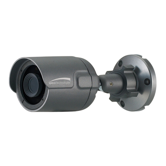
Page 6: Name And Function Of Each Part
Intelligent Video Motion detection 12 x 12 blocks Alarm Trigger Motion Detection, Tampering Alarm System Firmware Upgrade Remote Upgrade via Network Integration CGI Interface Document ActiveX Interface (ocx (dll) + document) Power Source DC 12V, POE (Power Over Ethernet) : 802.3af Power Consumption Physical Net Weight... -
Page 7: Name And Function
Top Rubber x 1 Junction Box x 1 Sponge x 1 Tapping screw (Ø 4 x 30) x 4 Plastic anchor x 4 Screw PH (M4 x 8 ) x 3 Screw PH (M4 x 12) x 4 2.2 Name and Function ITEM DESCRIPTION DC12V... -
Page 8: Installation
Lens 3.6mm fixed lens Humidity sensor & Heater Digital Humidity and Temperature Sensor 3. INSTALLATION 3.1 How to mount to ceiling / wall Ceiling LAN Cable Power Ceiling Tile Plastic anchor x 3 (B) Bracket nut (A) L-Wrench Tapping screw (Ø 4 x 30) x 3... - Page 9 Ceiling_Junction Box Ceiling Tile Plastic anchor x 4 Junction Base Sponge Junction Box Assembly Tapping screw (Ø 4 x 30) x 4 Top Adapter Plate Top Rubber Finish with Super X Camera Ass'y PH (M4 x 8) x3 PH (M4 x 12) x4 ...
-
Page 10: 3-Axis Adjustment
3.2 3-Axis Adjustment ① Panning 360˚ Pan 360° Slightly loosen Pan Bracket nut then adjust pan of the camera and tighten the Bracket nut. Bracket nut ② Tilt 90˚ Slightly loosen Tilt bolt then Tilt 90° adjust tilt of the camera and tighten the bolt firmly. - Page 11 3.3.3 Accessing the Camera’s Web Setup Page 1) Open the browser and enter the camera’s IP address in the address bar or double click the device in IP Scanner. Enter the IP address here 2) Enter the user name and password when prompted. 3) Default user name is admin and password is 1234.
-
Page 12: Dimensions (Mm)
4. DIMENSIONS (mm)
Need help?
Do you have a question about the Intensifier O2iB68 and is the answer not in the manual?
Questions and answers