
Related Manuals for MRC REAC-N10LE-3


Summary of Contents for MRC REAC-N10LE-3
- Page 1 Three layer Laboratory Reactors REAC-N10/20/30/50LE-3 User Manual 3, Hagavish st. Israel 58817 Tel: 972 3 5595252, Fax: 972 3 5594529 mrc@mrclab.com MRC. 10.22...
-
Page 2: Table Of Contents
CONTENTS GENERAL ..........................1 ..........................1 REFACE ....................... 1 AFETY NSTRUCTION User’s Qualification ....................1 1.2.1 1.2.2 Intended Use ......................1 1.2.3 Improper Use......................1 1.2.4 Warning Signs ......................2 1.2.5 Hazards Related to the Instrument ................3 1.2.6 Other Dangers ......................4 1.2.7 Safety Measures ....................... - Page 3 MAINTENANCE AND MANAGEMENT ............... 17 ........................ 17 ANAGEMENT ........................17 LEANING ......................18 ROUBLESHOOTING...
-
Page 4: General
General Preface Thanks for choosing ‘REAC-NxxLE-3 series speed-regulation glass reactor’. This operation manual introduced installation, operation, maintenance of glass reactors. Before using the instrument, please read this manual carefully 1.2 Safety This chapter describes the safety rules during installation and operation of ‘REAC-NxxLE-3 series speed-regulation glass reactors’. -
Page 5: Warning Signs
b) Used in the places where the power supply is not in conformity with the requirements. c) Used in high magnetic fields or corrosive environment. d) Used to deal with Hydrofluoric acid solution. e) Used to deal with hard, brittle materials (such as stones, soil samples, etc.), which may cause damage to the glass vessel. -
Page 6: Hazards Related To The Instrument
Reminder Reminder It may cause damage to the instrument. Please pay extra attention to all warning signs. 1.2.5 Hazards Related to the Instrument Please pay attention to the following safety instructions: Danger Prohibited to use it in explosive gas environment or explosive dust environment. -
Page 7: Other Dangers
and impacting the inside and outside of the glass. The circulating liquid pressure in the jacket should not exceed 0.03MPa, otherwise the glass vessel will be damaged. Ensure that the circulating fluid in the pipeline flows smoothly, and the pressure of circulating liquid should not exceed 0.03Mpa. -
Page 8: Safety Measures
1.2.7 Safety Measures Please wear personal protective equipment when operating this instrument, such as protective glasses, protective clothing and gloves. Brief Introduction of the Instrument 1.3 REAC-NxxLE-3 Series Lifting type speed-regulation glass reactors are mainly used for synthetic reaction, distillation and concentration of different types of materials. It can be divided into three types according to structure: single-wall, double-wall and triple-wall The reactor can be vaccumized to a negative pressure state according to some experimental requirements. -
Page 9: Technical Data
Technical Data Table Technical data Model Item REAC-N50LE-3 REAC-N10LE-3 REAC-N20LE-3 REAC-N30LE-3 Jacket inlet pressure (MPa) ≤0.03 Pressure inside reaction vessel (MPa) Vacuum to normal pressure -80—200 Working temperature range (℃) Stirring speed (r/min) 20—500 Display window Volume of glass vessel (L) 10.0... -
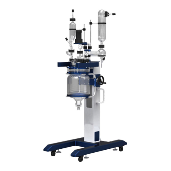
Page 10: Instrument Configuration
1.5 Instrument Configuration Take REAC-N50LE-3 as reference 1.Upper pole 2. Silicon rubber shroud ring 3. Rotary motor 4. Constant-pressure funnel 5. Aluminum flange 6.Connection elbow of constant-pressure funnel 7. Vacuum gauge 8. Reactor lid 9. Upper tray 10. Middle tray 11. -
Page 11: Unpacking And Installation
Unpacking and Installation Unpacking and Installation After unpacking the package, please find the operation manual and read it carefully; inspect all parts according to the packing list. Move out the frame carefully; put it on the floor steady, and lock the 4 swivel casters. Before installation, please clean the glass parts carefully to make sure it will meet the test requirements. - Page 12 dispenser (17) is placed on the tray (38). Connect the condensing dispenser (17) to the lid (8), adjust the position of the tray (38), use the flange (5) to connect the condensing dispenser (17) and lid (8); use the flange (5) to connect Condenser (15) and condensate dispenser (17), surround the rubber bracket (2) around the upper center of the condenser (15) and then lock 2.2.2 Installation of stirrer shaft 8 Reactor lid...
- Page 13 Figure 2.2.3 Installation of motor kit 16Motor support 24 Stirring paddle 25 Stirrer shaft 32Support frame 33Universal coupling 34 Motor kit Figure 2.2.4 Installation of Condenser joint 15 Condenser 35 Flat sealing ring 36 Connector 37 Nut...
-
Page 14: Installation Of Temperaure Sensor
Figure 2.2.5 Installation of Condensing Kit 2 Rubber bracket 5 Flange 8 Reactor lid 15 Condenser 17 Condensing dispenser 38 Tray 2.2.6 Installation of Temperature Sensor The temperature sensor and the sensor base have been assembled together already, just put it into the right port on the reactor lid. -
Page 15: Installation Of Constant-Pressure Funnel And Vacuum Gauge
8 Reactor lid 39 Material Charging Port Sealing Kit 40 Bolt 41Retaining ring 42Nut 2.2.8 Installation of Constant-pressure Funnel and Vacuum Gauge Please install the constant-pressure funnel and vacuum gauge according to figure 2.2.8. Figure 2.2.8 Installation of Constant-pressure Funnel 1 Pole 2 Rubber bracket 4Constant-pressure funnel... -
Page 16: Installation Of Operation Box And Motor Controller
Figure 2.2.9 Installation of Discharge valve 5 Flange 11 Glass vessel 13 Discharge valve 43Retaining ring 44 Sealing gasket 2.2.10 Installation of Operation Box and Motor Controller Fix the Operation box (19) and Motor Controller(23) on the frame(21), please see chapter 1.5. -
Page 17: How To Connect The Glass Reactor With Vacuum Pump And Temperature Control
46 DN15high temperature ball valve 48 U-type 45 Connector 47 Three-way adapter fixed mount 49 Gasket 50 Stainless steel hose 51 Connection elbow How to connect the glass reactor with vacuum pump and temperature control unit Connect the glass reactor with Vacuum Pump and the Dynamic Temperature Control System properly, please refer to Figure 2.3. -
Page 18: Operating
Operation Caution Table 3.1 Caution Please read this manual carefully before using the reactor. Please place the reactor steadily on the floor, then lock the swivel casters. The best ambient temperature for this device is 5—35℃. It might cause any failure to the machine if it works for a long time beyond this temperature range. -
Page 19: Operation
manufacturer. Maximum permissible temperature difference between reaction vessel and the jacket is not more than 80℃ (ΔT<= 80℃). Please do not move the reactor when it is working. Beware of scaling! Please wear glasses when dealing with the sample. Do not move it when the temperature of the vessel >=80℃! Do not refit this device. - Page 20 9) Discharge the material from the draining port (14). After emptying the material, please disassemble the draining valve and clean the glass part and the PTFE stopper. 10) Reinstall the draining valve. Notice: a) When discharging the materials, slowly turn the black stopper at the bottom of the discharge valve counterclockwise.
- Page 21 Do not use brushes, grinding powder, acid, petrol or other solvents to clean the surface of the body to avoid damage to the protective layer. The reactor body and its glass components may be very hot or very cold, beware of burns or frostbite! Please clean it when the glass device is close to room temperature.
- Page 22 vacuum degree parts Sealing ring damaged Replace it Sealing ring installed not in Re-install it place Hose aging Replace it...
Need help?
Do you have a question about the REAC-N10LE-3 and is the answer not in the manual?
Questions and answers