Table of Contents
Advertisement
Quick Links
Instruction ManualV1.0
mKey access control
1 Product overview
1.1 Product introduction
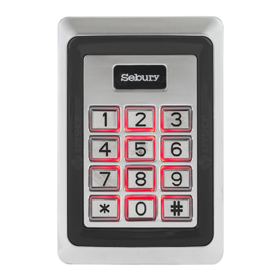
This product uses high-strength zinc alloy body, Proximity card (EM card, also known as ID card)
or password to open the door, built-in highly integrated microcontroller, simple circuit, safe and
reliable, economical and durable, suitable for office, villa etc.
1.2 Features
> 1000 user cards bound with 1000 user passwords, and the user can modify password by himself;
> Opening door modes: card, card + PIN, card or PIN, PIN.
> Opening time: 50mS, 1-98 seconds for normal mode, 99 seconds for switch mode;
> Electric lock mode: power-on unlocking (such as electric rim lock, electric strike), power-off
unlocking (such as electric bolt, magnetic lock);
> Built-in high-current MOS tube can directly drive the electric lock, and can resist strong
magnetic unlocking;
> Safe mode can be set: 10 times invalid card or password will automatically lock the machine for
10 minutes;
> Can connect with an exit button, convenient to open the door from inside.
> Safety screw at the bottom can prevent malicious destroy.
Advertisement
Table of Contents

Related Manuals for Sebury mKey


Summary of Contents for Sebury mKey
- Page 1 Instruction ManualV1.0 mKey access control 1 Product overview 1.1 Product introduction This product uses high-strength zinc alloy body, Proximity card (EM card, also known as ID card) or password to open the door, built-in highly integrated microcontroller, simple circuit, safe and reliable, economical and durable, suitable for office, villa etc.
- Page 2 1.3 Functional component 1.4 Technical parameters > Working voltage: DC12±2V > Static current: ≤20mA > Operating current: ≤100mA > Drive electric lock current: ≤3A > Working environment temperature: -20~50°C > Working environment humidity: 0~95% (no condensation) > Maximum card reading distance:5cm 2 (Installation, wiring and Debugging) 2.1 Installation Unscrew the anti-tamper screw on the bottom of the product with the special anti-tamper...
- Page 3 2.2Wiring According to the selected wiring diagram, connect the four lead wires to the system cable one by one, and then insert one end of the plug into the 4P socket of the access control, taking care not to short circuit, otherwise the power may be burned out. After the check is correct, briefly power on to test if the indicator light is normal, and if the buzzer will beep once, if not please cut off the power immediately, and check the wiring again.
- Page 4 2.3 Debug Turn on the power supply and test according to the instructions. The debugging will be completed until the lock can be opened correctly by reading card, password and exit button. 3 Basic functions Operating conventions: > A long sound"Di-"indicates correct operate. Three short sounds"Di Di Di"indicate wrong operate .
- Page 5 3.2 Change the master code Press 0 new code # new code # For example, change master code to 999999, press 0 999999 # 999999# 3.3 Add card user Below 3 methods to add a card user, the ID number range is 0-999, the user password is fixed to 6 digits, and it can be operated continuously.
- Page 6 3.5 Setting the door opening method 3 0 # Open the door by card. 3 1 # Open the door by card plus password. 3 2 # Default value, open the door by card or password. 3 3 # Open the door by password. Example, set the card plus password to open the door: 3,1#.
- Page 7 3.10.2 Change password by ID number * (ID number) # (old code) # (new code) # (new code) # Example Change user’s password by ID, *1#123456#111111#111111# Note: when changing password by ID number,the old user password can not be initial password 1234 3.11 User to open the door Read the card or enter 6 digits user’s passwords, or press the Exit button...
- Page 8 5 Simple Troubleshooting...
Need help?
Do you have a question about the mKey and is the answer not in the manual?
Questions and answers