Table of Contents
Advertisement
Quick Links
1.Product Introduction, Features & Technical Parameters
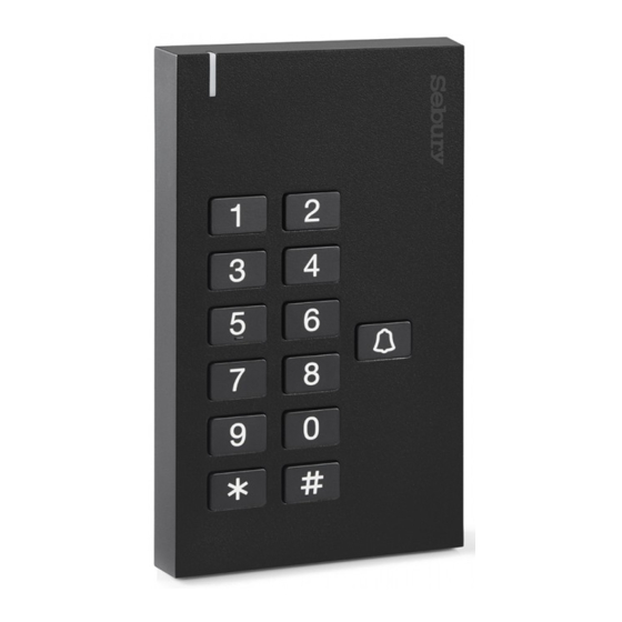
1.1 Introduction:
Q3 support EM or PIN to control single door, can drive electric lock, connect
exit button, door magnetic detection and door bell button, also can be used as
Reader working with controller. 500 pcs user capacity and each user owns one
card and a 4-6 digits PIN.
1.2 Features:
> Use RFID to open door, fashion, security and reliability.
> Can be used as controller and reader, freely switch, easily operate.
> Clear and beautiful luminous keypad, convenient for user to enter
password & open door.
> With door bell button, convenient for visitor.
> 500 pcs user capacity, suit for office, villa and household use etc.
> Wiring is very simple; can be done by users without professional knowledge;
can be connected with various electric lock and no need to change external
wiring.
> Every user can change the password without master.
> Password is 4-6 digits, more security.
> Multiple output format of pressing key, can work with types of controller.
> Anti-vandal, door magnetic detection alarm function.
1.3 Technical Parameters:
> Input voltage: DC12~24V
> Idle current:
≤
20mA
> Max reading distance: 5-8cm
> Frequency: 125KHz
> Door bell output load: ≤ 10mA
> Lock output load: ≤ 3A
> Output format of card No.: Wiegand26
> Output format of pressing one key: 4bit, 8bit
> Dimension: 130mm×75mm×17mm
> Operating temperature: -40~60° C
> Operating humidity: 0~95% (non-condensing)
2. Installation And Wiring Diagram
2.1 Following the figure and draw the installation and cable hole on the wall.
Use φ6mm drill bit for drilling two installation hole and φ10mm drill bit for
drilling cable hole.
2.2 Insert rubber bungs to installation hole, fix the back shell of controller on the
wall.
② A PIN 1234 will be generated automatically when we add a card user; it is
only for changing new PIN, not to open door.
③ After a card is added, you can continue to add other cards or PIN without
exiting current setting mode and start over.
④ A type of lock refers to those lock that normally under standby status ,there
is no current for lock, when there is current the door will open, such as
electrified lock, electric strike.
⑤ B type of lock refers to those lock that normally under standby status, there
is current for lock, when there is no current the door will open, such as
electromagnetic lock, electric drop bolt.
4. User Operation
4.1 Swiping Card to open door:
Swiping user card once , door will be opened.
4.2 Swiping Card+PIN to open door:
Swiping user card once, and enter 4-6digits PIN,# , door will be opened.
4.3 Card or PIN to open door:
Swiping user card once or enter4-6digits PIN, # , door will be opened.
4.4 Change the user's PIN
* , Swipe user card, Enter 4-6 digits old PIN,# , Enter 4-6 digits new PIN,# ,
Repeat Enter 4-6 digits new PIN,# Or * , Enter 1-500(ID No.),#,
Enter 4-6 digits old PIN,# , Enter 4-6 digits new PIN,# ,
Repeat Enter 4-6 digits new PIN,#
Remarks: PIN users have to get the ID No. and initial PIN from master. Card
users have to swipe card when change the PIN first time.
4.5 Door bell:
Press door bell button on Q3, the connected external door bell will ring.
Note: External door bell should be low current (≤10mA).
5. Alarm Function
5.1 Anti-vandal alarm
If anti-vandal alarm function is on and when device is opened illegally, controller
will sound alarm.
5.2 Door Magnetic detection alarm
If the door is connected with magnetic contact, and is opened illegally or by
force, controller will sound alarm.
5.3 Remove the alarm
Swipe valid card or enter master's PIN can remove alarm. If there is no any
operation the alarm will stop automatically after 1 minute.
2.3 Pull controller's cable through the cable
hole, connecting the wire needed according
to wiring diagram.( use electrical tape to cover
the wire not used)
1
2.4 Plug 10P connection wire to PCB board of
controller; fasten the front cover on the back
shell with anti-vandal screw.
Installation Figure
+12V
LOCK+
LOCK-
Principle of Electronic Lock
Q3 Standalone Access Controller
Orange
Purple
Red
Black Green White Brown Yellow
Blue
+
_
+
DC 12V
Door Bell
_
Power
Wiring Diagram (DC Power Supply)
6. Reset To Factory Default
Power off, press "*" and power on, the LED turns into ORANGE in 1s, and then
release the button "*" after you hear " Beep Beep", And then you hear "Bee-eep",
the LED turns into Red means reset to Factory Default successfully. But it won't
delete all user information.
7. Sound And Light Indication
Operation Status
Color of LED
Buzzer
Stand by
Red
Pressing keypad
Beep
Swipe card
Bee-eep
Green
Unlocking
Bee-eep
Green
Green
Bee-eep
Successful
Fail
Beep Beep Beep
Entering PIN
RED flash slow
Swiping card under way
RED flash slow
of swiping card+PIN
First menu of setting
RED flash slow
Second menu of setting
Orange flash slow
Setting
Orange
Alarming
Red flash quick
Alarm sound
8. Card Reader Mode (Wiring Diagram As Below)
Q3 Standalone Access Control (Reader Mode)
D_IN
OPEN
(LED)
(BZ)
+12V
GND
D0
D1
LOCK+ LOCK-
BELL_A BELL_B
Red
Black Green White Brown Yellow
Orange
Purple
Blue
+12V GND
D0
D1
LED
BZ
Door Bell
Access Control
To use the card reader function, first set the machine for card reader mode, it
has following functions:
When LED level is low, LED light will turn into Green, after 30 seconds or LED
level rising, LED light will return to normal.
When BZ level is low, the Buzzer will beep, after 30 seconds or BZ level rising,
the Buzzer will return to normal.
Q3 Standalone Access Controller
Special Power Supply
PUSH
+12V
When connect Special
power supply, need set
to connect A type Lock
and door relay time 50ms.
Wiring Diagram(Special Power Supply)
3. Master Setting
Note that all the following programming should be under master programming
mode.
When master's PIN is wrong and the time is over 5s before you enter PIN again,
it will return to standby mode. After enter right master's PIN, it will also return to
standby mode if there is no valid operation in 30 seconds. Press "#" to confirm
the input number, return to previous menu by press "*", the indicator light will
indicate the operation mode.
Grey
To enter the master programming mode
Red
Red Flash
Functions
6-8 digits master's
To enter the programming
mode
PIN #
Both card number and pressing keypad output in Wiegand format, output data
is transmitted by the Low Level of D0 & D1 wire:
D0: Low level means 0, green wire
D1: Low level means 1, white wire
The Pulse width for low level is 40uS; and the time interval is 2mS.
2mS
D0
+5V
40uS
0V
2mS
D1
+5V
40uS
0V
Output format of card number is Wiegand 26.
Output format of pressing keypad can be set 3 formats:
Format 0: virtual card No. , namely enter 4-6 digits PIN, #, output a 10bits card
number in Wiegand 26 format. For example, enter a password 999999, the
output card number is 0000999999, could be displayed as a 10bits decimal
card number on a equipment which support to display it.
Format 1: 4 bit of pressing one key, which is pressing every single key, output
a 4bit data, the corresponding relationship is:
1 (0001) , 2 (0010) , 3 (0011)
4 (0100), 5 (0101 ) , 6 (0110)
7 (0111) , 8 (1000) , 9 (1001)
* (1010) , 0 (0000) , # (1011)
Format 2: 8 bit of pressing one key, which is pressing every single key, output
a 8bit data, the corresponding relationship is:
1 (11100001) , 2 (11010010) , 3 (11000011)
4 (10110100) , 5 (10100101) , 6 (10010110)
7 (10000111) , 8 (01111000) , 9 (01101001)
* (01011010) , 0 (11110000) , # (01001011)
Grey
9. Packing List
Name
Model No
Qty.
Access controller
Q3
1
10P connection wire
1
User manual
Q3
1
Rubber Bung
2
Used for fixing installation
Self-tapping Screw
Φ4mm×25mm
2
Used for fixing installation
Special Screwdriver
Special tool of security screw
1
Access Controller Setting
Red
Orange
Flash
6-8 digits new PIN # repeat
0
6~8 digits new PIN #
Read card
1-500(ID), #, Read card
GND
NO
COM
NC
1
8 or 10 digits card number
#
1-500(ID),#,8 or 10 digits card
+
+
number #
1-500(ID), #,4-6 digits PIN, #
Read card
8 or 10 digits card number, #
2
1-500(ID),#
0000, # (Note: This is a
2
-
-
dangerous option, so use with
care)
0, #
1, #
3
2, #
0, #
4
1-99, #
0, #
5
1, #
Reader Setting
Red
Orange
Orange
Flash
Flash
0, #
Reader mode
1
1, #
Access controller mode
7
0, #
Virtual card No.
Remark
4Bit of pressing one key
3
1, #
Factory default
2, #
8Bit of pressing one key
888888
Note:
① 8 digits card No., for example 118, 32319, some cards have no the first 3
digits 118, remain 32319, in this case, add card user by reading card but not
enter card number.
10 digits card No., for example 0007765567, some cards have no the first 3
digits 000, remain 7765567, in this case, you need enter 000 before 7765567
to add this card user.
Q3
Standalone Access
Controller/ Reader
Remark
User Manual
Functions
Remark
To change the master's PIN
To add card users
Rotate
Operation
To add PIN users
Delete one card
Rotate
Operation
Delete one user
Delete All users
Entry by Card only
Entry by Card and
Factory
PIN together
default 2
Entry by either card or PIN
To set door relay time 50mS
Factory
To set door relay time 1-99S
default 5s
Connect to A type of lock
Factory
Connect to B type of lock
default 1
Functions
Remark
Factory
default 1
Factory
default 1
Advertisement
Table of Contents


Need help?
Do you have a question about the Q3 and is the answer not in the manual?
Questions and answers