
Related Manuals for Festo MPS PA Station


Summary of Contents for Festo MPS PA Station
- Page 1 8079866 Bottling Learning System MPS PA Stations Operating instructions Festo Didactic 696690 en 09/2019...
- Page 2 09/2019 V3.0.1 Authors: Jürgen Helmich, Frank Ebel Layout: Festo Didactic © Festo Didactic SE, Rechbergstraße 3, 73770 Denkendorf, Germany, 2019 +49 711 3467-0 www.festo-didactic.com +49 711 34754-88500 did@festo.com Reproduction, distribution and utilisation of this document, as well as the communication of its contents to others without explicit authorisation, is prohibited.
-
Page 3: Table Of Contents
8.2.3 RI flow diagram _________________________________________________________________ 25 8.3 Function of the level system __________________________________________________________ 26 8.4 Pump _____________________________________________________________________________ 27 8.5 Level monitoring ___________________________________________________________________ 27 8.5.1 Capacitive proximity sensors ______________________________________________________ 28 8.5.2 Float switch ____________________________________________________________________ 28 8.5.3 Ultrasonic sensor _______________________________________________________________ 28 © Festo Didactic 696690... - Page 4 11.5.2 Cable connections between control console and PLC EduTrainer ________________________ 46 11.5.3 Establishing 1-bit communication connections ______________________________________ 46 11.5.4 Load sample project ____________________________________________________________ 49 11.5.5 Starting the sequence __________________________________________________________ 50 11.5.6 Operation on the control console with operator unit TP700 Comfort _____________________ 50 © Festo Didactic 696690...
- Page 5 12.4 Error in the electrical system _________________________________________________________ 61 12.5 Mechanical faults __________________________________________________________________ 61 12.6 Error due to parameterization ________________________________________________________ 62 13 Further information and updates ________________________________________________________ 63 14 Disposal ____________________________________________________________________________ 63 15 List of figures ________________________________________________________________________ 64 © Festo Didactic 696690...
- Page 6 Bottling Learning System © Festo Didactic 696690...
-
Page 7: General Requirements For Operating The Devices
Damaged devices must be banned from further use and removed from the laboratory or classroom. – Damaged connecting cables, pneumatic tubing and hydraulic hoses represent a safety risk and must be removed from the laboratory or classroom. © Festo Didactic 696690... -
Page 8: Pictograms
Strong optical radiation. Non-observance may result in severe personal injury. CAUTION ... indicates a possibly hazardous situation which may result in moderate or slight personal injury if not avoided. Hot surfaces. Non-observance may result in burns. © Festo Didactic 696690... - Page 9 Electric shock Laser beam Strong optical radiation Hot surfaces Danger of crushing Infeed by rotating rollers Loud noises Lifting heavy loads Warnung vor ungewolltem Einzug © Festo Didactic 696690...
-
Page 10: Intended Use
Festo Didactic hereby excludes any and all liability for damages suffered by trainees, the training company and/or any third parties, which occur during use of the device in situations that serve any purpose other than training and/or vocational education, unless such damage has been caused by Festo Didactic due to malicious intent or gross negligence. -
Page 11: For Your Safety
Festo Didactic components and systems. In particular, the safety instructions must be adhered to by all persons who work with Festo Didactic components and systems. Furthermore, all pertinent accident prevention rules and regulations that are applicable at the respective place of use must be adhered to. -
Page 12: Dangers When Handling The Components And Systems
4.4 Dangers when handling the components and systems Festo Didactic systems and components are designed in accordance with the latest technology and recognized safety rules. However, life and limb of the user or third parties may be endangered and the machine or other property may be damaged during their use. -
Page 13: Work And Safety Instructions
Use a tool to operate the limit switches, for example a screwdriver. • Set all components up so that it’s easy to activate the switches and interrupters. • Follow the instructions regarding positioning of the components. © Festo Didactic 696690... -
Page 14: Electrical System
The power supply unit must be operated only with a power supply with a grounding conductor. • Establishing and disconnecting electrical connections – Electrical connections may be established only in the absence of voltage. – Electrical connections may be disconnected only in the absence of voltage. © Festo Didactic 696690... -
Page 15: Pneumatics
Do not disconnect tubing while under pressure. • Do not attempt to seal or plug pneumatic tubing or plug connectors with your hands or fingers. • Risk of injury when switching on compressed air! Cylinders can advance and retract automatically. © Festo Didactic 696690... -
Page 16: Process Technology
The liquid in the station can be drained by opening the drain valves! • No liquid should be left in the system for a long period of time, as bacteria such as Legionella can form in it. © Festo Didactic 696690... -
Page 17: Technical Data
Volume of the dosing tank / Main tank max. 3 l / 10 l Dimensions of the station 700 x 700 x 920 mm Dimensions of the profile plate 700 x 700 x 32 mm Weight 48 kg Subject to change © Festo Didactic 696690... -
Page 18: Pin Allocation Table
0 V power supply for outputs GND A Purple GND B 0 V power supply for inputs GND B 23+24 White-blue Note Cable jumpers are connected from emergency off to bit 1.5 on all preferred PLC versions. © Festo Didactic 696690... -
Page 19: Analog Terminal
24 V B 24 V power supply for inputs GND B 0 V power supply for inputs Pink 24 V A 24 V power supply for outputs GND A 0 V power supply for outputs Green © Festo Didactic 696690... -
Page 20: Control Panel
0 V power supply for inputs 23+24 White-blue Note Communication input I5 is used as an EMERGENCY-STOP signal input in PLC EduTrainers. The inputs and outputs of the control panel are located on the second byte of the EduTrainer. © Festo Didactic 696690... -
Page 21: Transport/Unpacking/Scope Of Delivery
The crate may only be transported with a suitable pallet jack or forklift. The crate must be secured against tipping over and falling. – Report transport damage without delay to the freight forwarder and Festo Didactic. 7.2 Unpacking Carefully remove the padding material from the crate when unpacking the station. When unpacking the system or station, make sure that none of its assemblies have been damaged. -
Page 22: Setup
1x I/O data cable with SysLink connectors to IEEE 488, crossed (order no. 167106) • 1x analog cable, parallel (order no. 529141) • Safety laboratory cable, 3 m (order no. 571817) • Control console with SIMATIC Touch Panel TP700 (order no. 8079869) © Festo Didactic 696690... -
Page 23: The Bottling Station
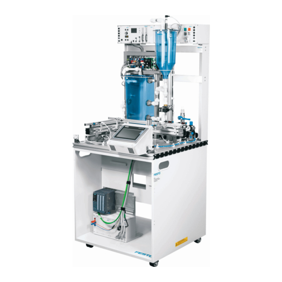
After selecting a recipe, either a certain number of bottles is filled with the liquid from the dosing tank or in continuous operation any number of bottles. The following control functions can be edited: • Level system with PID controller (main function) Figure 2: Bottling station (Figure, similar) © Festo Didactic 696690... -
Page 24: Main Components
Aluminum profile plate 700 x 700 159410 540691 Start-up valve with filter control valve 540691 Set of bottles, 20 containers D = 40 mm / H = 60 mm / V = 50 ml with 20 caps 567202 © Festo Didactic 696690... -
Page 25: Small Parts Included In The Scope Of Delivery Of The Station
4 mm safety laboratory cables, 300 mm, blue 8092631 4 mm safety laboratory cables, 1500 mm, black 8092659 4 mm safety laboratory cables, 1500 mm, blue 8092658 8.2.3 RI flow diagram Figure 3: RI flow diagram as per ISO10628 and EN 62424 © Festo Didactic 696690... -
Page 26: Function Of The Level System
BL1 and should be kept constant in continuous operation even after faults or setpoint jumps. Figure 4: Level system As a disturbance variable, the manual valve VV2 can be opened in continuous automatic mode. © Festo Didactic 696690... -
Page 27: Pump
Float switch in the cover of the dosing tank and lateral installation in the main tank as overflow protection Ultrasonic sensor for sensing the minimum level in the dosing tank. Figure 6: Level monitoring with capacitive proximity sensors © Festo Didactic 696690... -
Page 28: Capacitive Proximity Sensors
The ultrasonic sensor measures the level in the dosing tank and is adjusted in such a way that it supplies a small voltage at a low level and a larger voltage at a higher level (inverted characteristic curve, 0...10 V). Figure 8: Analog ultrasonic sensor © Festo Didactic 696690... -
Page 29: Conveyor Belts With Diffuse Light Sensors
Caution Laser beam Avoid looking directly into the laser beam. The guardrails and diffuse light sensors are mechanically mounted for bottles with a height of 60 mm. An adaptation to bottles with height 25 mm is possible. © Festo Didactic 696690... -
Page 30: Pneumatic Separator
Figure 11: Separator Caution Tthere is a danger of crushing with the separating stop! Do not interfere with the movement of the actuator while the process is running. Caution Loud noises are generated when the actuator is moving! © Festo Didactic 696690... -
Page 31: 2/2-Way Dosing Valve
As a maintenance unit, a filter control valve with pressure gauge and switch-on valve for compressed air supply is mounted on a swivel mount. The on-off valve pressurizes and exhausts the connected MPS PA Station. The station accessories included in the station scope of delivery include: •... -
Page 32: Electrical Connection Technology
9. 2-fold changeover relay for overflow protection circuit: if a tank is overfilled, the float switch opens, the relay drops out and interrupts the power supply to the pump motors. 10. Wiring terminals for overflow protection circuit © Festo Didactic 696690... -
Page 33: Mounting Frame
The mounting frame (1) of the MPS-PA station consists of a single-line ER frame for the connection board (2) and a 19″ frame (3) for 19″ mounting plates. The connection board is plugged into the ER frame. Figure 15: ER mounting frame © Festo Didactic 696690... -
Page 34: 19" Frame
There is a risk of electric shock if used improperly! With the MPS PA 204 system, a 19″ EMERGENCY-STOP panel is added as an option to the 19″ frame of the Filtration and Reactor stations. © Festo Didactic 696690... -
Page 35: Plc Edutrainer Universal S7-1512C
The support system of the EduTrainer Universal, size 1 (W x H) 305 x 300 mm, can be placed on a table or in an MPS PA station. The 19″ module with 2x SysLink connector with 8 digital inputs and 8 digital outputs each and 1x D-Sub 15-pin connector with 4 analog inputs and 2 analog outputs establishes the signal connections to the MPS PA station and the control panel. -
Page 36: Control Console With Operator Unit Tp700 Comfort
EasyPort is used to connect a PC to actual hardware. Figure 18: EasyPort 19″ USB Optionally, the binary control of the process with the digital technology module or the GRAFCET can be created in combination with FluidSim. © Festo Didactic 696690... -
Page 37: Usb Device Server
In addition, several users can access the learning scenario one after the other. 8.15 Trolley 700 The trolley makes an MPS PA Station a compact and mobile unit. The station is mounted on the trolley. The EduTrainer Universal, size 1, can be inserted and the emergency stop board attached. -
Page 38: Operation
Communication between the MPS PA stations takes place via 4mm safety laboratory cables and the communication fields, as with MPS-D stations. Tank overflows in the Bottling station are monitored using float switches. The overflow protection is coupled to upstream and downstream stations using an optical transmitter and receiver. © Festo Didactic 696690... -
Page 39: Sequence Description
8. Remove the bottle or convey it further. 9. Continue with 4. if the number < target value 10. Message “Recipe ready” when nominal quantity has been reached 11. End The STOP function switches the actuators off at any time. © Festo Didactic 696690... -
Page 40: Automatic Mode, Continuous Bottling
The STOP function switches the actuators off at any time. Recipe Time Filling quantity of dosing tank Recipe A “25 ml” Approx. 600 ms Recipe B “50 ml” Approx. 2000 ms Caution! Not for small bottles! © Festo Didactic 696690... -
Page 41: Manual Mode
The sequence can be interrupted at any time by pressing the EMERGENCY-STOP button or by pressing the STOP button. • The following applies when several stations are combined: The individual stations are aligned in the order opposite the direction of material flow. © Festo Didactic 696690... -
Page 42: Commissioning
Bottling Learning System 11 Commissioning The stations of the MPS PAs are generally • Fully assembled • Individually adjusted and ready for use • Pre-commissioned • Tested Figure 22: Flow chart for commissioning an MPS PA station. © Festo Didactic 696690... -
Page 43: Workstation
All components, tubing connections and cabling are clearly identified, so that all of the connections can be readily restored. 11.1 Workstation To commission the MPS PA station with the sample programs you will need: • the mounted and adjusted MPS PA station •... -
Page 44: Power Supply
11.5 Actuation with PLC EduTrainer and control console 11.5.1 Cable connections between station and EduTrainer PLC The cable connections are described and shown for an MPS PA station connected to a PLC control without power supply in the EduTrainer Universal as MPS-PA preferred variant: •... - Page 45 SysLink I/O data cable, parallel (034031) Analog cable, 15-pin, parallel (529141) Laboratory cable with safety laboratory sockets (red/blue) SysLink I/O data cables, parallel (034031) Figure 24: Cable connection MPS PA Station - EduTrainer Universal without power supply © Festo Didactic 696690...
-
Page 46: Cable Connections Between Control Console And Plc Edutrainer
The communication connections to the other stations must be established according to the following examples. The examples are general, but apply equally to all stations. Any deviations from this standard will be pointed out. Example of I/O push-in connectors between 19″ frames Figure 25: Communication connection between 19″ frames © Festo Didactic 696690... - Page 47 Figure 27: MPS and MPS-PA combination Bottles are transported from the Distributing/Conveyor station to the Bottling station and filled there. They are then transported to the Joining station and covered. At the end, sorting takes place in the slides. © Festo Didactic 696690...
- Page 48 1. Connect the sockets Q5 and GND of the Bottling Station (1) to the sockets I6 and GND of the Distributing/Conveyor station (2). 2. Connect the sockets I7 and GND of the Bottling Station (1) to the sockets Q4 and GND of the Joining Station (3). © Festo Didactic 696690...
-
Page 49: Load Sample Project
3. Start the TIA-Portal development environment 4. In the de-archived project (see above), select the corresponding sub-project of the station “tpBottling”. 5. Load the project into the operator unit. Help can be found at Getting Started. © Festo Didactic 696690... -
Page 50: Starting The Sequence
Check whether the PLC is in operation and the program is loaded. Main menu If all the components are in operation, the main menu appears on the control console. Figure 29: Main menu screen © Festo Didactic 696690... - Page 51 3. In the main menu, select the “Automatic” button. 4. Select your bottle size and the button for the process type of the filling station: batch or continuous filling mode (see chapter 10.4 Sequence). Figure 30: Automatic operation screen © Festo Didactic 696690...
- Page 52 If the container VE1 is empty, the message “Fill container VE1” appears in the information field. When the recipe is finished, you will receive the message "Recipe ready". 8. Use the "Back" button to return to the main menu. © Festo Didactic 696690...
- Page 53 Figure 34: Operating screen for manual operation – Control value of the pump 6. Set the control value directly or using the arrow buttons. Read the actual value of the filling quantity on the display. 7. The “Back” button returns you to the main menu. © Festo Didactic 696690...
- Page 54 4. The manipulated variable, actual value and setpoint value of the filling quantity are displayed in the curve diagram. Figure 36: “Trend” operator screen with the curve diagram 5. The “Back” button returns you to the main menu. © Festo Didactic 696690...
-
Page 55: Actuation With Easyport 19
11.6 Actuation with EasyPort 19 “ Cable connections between station and EasyPort 19 " The cable connections are for one MPS PA station connected to EasyPort 19 ”described and illustrated: • Connect digital I / Os of port 1 of the EasyPort and the I / O terminal (4) XD1 of the station with I / O data cable SysLink (6) or check the connection. -
Page 56: Adjusting Sensors
The proximity sensor must be triggered by the liquid in the tank. If there is no liquid in the tank, no signal may be present. 5. 4. Check the positioning and adjustment of the proximity switch by repeated filling and emptying of the tank. © Festo Didactic 696690... -
Page 57: Float Switch, Cover Installation
The ultrasonic sensor supplies an analog signal (0… 10 V) as a function of the filling level. Note The ultrasonic sensor can be used for both rising liquid levels and falling levels. © Festo Didactic 696690... - Page 58 The LED must light up already at a low water level. If this is not the case, the sensor must be readjusted using the mounting nuts. Note Make sure that the transmitter side of the sensor is always clean. © Festo Didactic 696690...
-
Page 59: Maintenance And Troubleshooting
The entire station Note Always use water of drinking water quality. If the MPS PA Station is not used for a longer period of time, the water should be drained off, the remaining water should be removed from the containers and pipes with a wet vacuum cleaner and rubbed dry with a lint-free cloth. -
Page 60: Error In The Piping System And Tanks
24VDC signal secure it with cable ties air tubing from the present at the 5/2W solenoid valve, hold the solenoid valve tubing tightly, switch the signal to the solenoid valve and check whether air escapes © Festo Didactic 696690... -
Page 61: Error In The Electrical System
Danger potential variable, or danger? Mechanical faults Lower tank VE1 Filling level via Incorrect or absent Turn the sensor or adjust Visual inspection of I/O capacitive sensors signal display the mounting bracket check along the profile © Festo Didactic 696690... -
Page 62: Error Due To Parameterization
EasyPort Connection to EasyPort Connection cannot be Set the EasyPort at the EasyPort using the established address, e.g. 2, Address buttons © Festo Didactic 696690... -
Page 63: Further Information And Updates
Bottling Learning System 13 Further information and updates Further information and updates of the technical documentation for the Festo Didactic components and systems are available at the following website: www.ip.festo-didactic.com 14 Disposal Electronic waste contains reusable materials and must not be disposed of with household waste. -
Page 64: List Of Figures
Figure 22: Flow chart for commissioning an MPS PA station................42 Figure 23: On-off valve with filter regulator ....................44 Figure 24: Cable connection MPS PA Station - EduTrainer Universal without power supply ......45 Figure 25: Communication connection between 19″ frames ................46 Figure 26: Communication connection between 19″... - Page 68 Festo Didactic SE Rechbergstraße 3 73770 Denkendorf Germany +49 711 3467-0 www.festo-didactic.com +49 711 34754-88500 did@festo.com...
Need help?
Do you have a question about the MPS PA Station and is the answer not in the manual?
Questions and answers