Festo MPS PA Manual
Pid controller
Hide thumbs
Also See for MPS PA:
- Operating instructions manual (64 pages) ,
- Operating instructions manual (68 pages)
Advertisement
Available languages
Available languages
Quick Links
Advertisement
Chapters

Related Manuals for Festo MPS PA


Summary of Contents for Festo MPS PA
- Page 1 ® PID-Regler Handbuch ® PID controller Manual 721946 DE/EN 08/07...
- Page 2 08/2007 Autoren/Authors: Frank Ebel, Markus Pany Grafik/Graphics: Doris Schwarzenberger Layout/Layout: 08/2007 © Festo Didactic GmbH & Co. KG, D-73770 Denkendorf, 2007 Internet: www.festo-didactic.com e-mail: did@festo.com Weitergabe sowie Vervielfältigung dieses Dokuments, Verwertung und Mitteilung seines Inhalts verboten, soweit nicht ausdrücklich gestattet.
-
Page 3: Table Of Contents
PA ________________________ 11 Kabelverbindungen _________________________________ 11 Programm installieren _______________________________ 15 Programmsprache einstellen __________________________ 16 Projekt laden ______________________________________ 17 Kontaktbelegungstabelle ____________________________ 23 Ein-/Ausgänge (analog) ______________________________ 23 Technische Daten __________________________________ 25 Elektrische Schaltpläne ______________________________ 26 © Festo Didactic GmbH & Co. KG • 721946... - Page 4 Install software _____________________________________ 37 Changing the software language_______________________ 38 Downloading the project _____________________________ 39 Contact allocation table _____________________________ 45 Inputs/outputs (analogue) ___________________________ 45 Technical data _____________________________________ 47 Electrical circuit diagrams ____________________________ 48 © Festo Didactic GmbH & Co. KG • 721946...
-
Page 5: Bestimmungsgemäße Verwendung/Intended Use
Festo Didactic herewith excludes any liability for damage or injury caused to trainees, the training company and/or any third party, which may occur if the system is in use for purposes other than purely for training, unless the said damage/injury has been caused by Festo Didactic deliberately or through gross negligence. -
Page 6: Einleitung
® PA-System integriert. Die analogen Ein- und Ausgänge sind auf zwei Anschlussbuchsen SysLink-Analog (Sub-D) verdrahtet. Die Pin-Belegung entspricht der SysLink-Schnittstelle des Modularen Produktions-Systems Prozess ® Automation (MPS PA) von Festo Didactic. © Festo Didactic GmbH & Co. KG • 721946... -
Page 7: Sicherheitshinweise
Beachten Sie die Angaben der Datenblätter zu den einzelnen Elementen, insbesondere auch alle Hinweise zur Sicherheit! Elektrik Herstellen bzw. abbauen von elektrischen Verbindungen nur in spannungslosem Zustand! Verwenden Sie nur Kleinspannungen, maximal 24 VDC. © Festo Didactic GmbH & Co. KG • 721946... -
Page 8: Aufbau Und Funktion
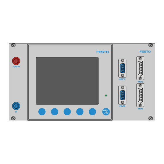
24 V-Spannungsversorgung mit 4 mm Sicherheitsbuchsen RS232 (EIA232) serielle Programmierschnittstelle Anschlussbuchse (Sub-D) SysLink-Analog zu Station/IO-SIM (XMA3) Anschlussbuchse (Sub-D) SysLink-Analog zu SPS-Board/IO-SIM (XMA4) PB-DP Profibus DP Kommunikationsschnittstelle EXIT/Handbetrieb-Taste Spannungsversorgungs-LED Bedienfeld-Tasten Abbildung PID-Regler mit Anschlussplatte © Festo Didactic GmbH & Co. KG • 721946... -
Page 9: Lieferumfang
Durch doppelte Spannungsversorgung sind Materialschäden an der Simulationsbox möglich. Durch das digitale E/A-Datenkabel wird die Simulationsbox mit Betriebsspannung versorgt. Deshalb darf keine separate Spannungsversorgung angeschlossen werden! Bei Verwendung des analogen E/A-Datenkabels ist eine separate Spannungsversorgung erforderlich! © Festo Didactic GmbH & Co. KG • 721946... -
Page 10: Einbauweise
Netzgerät Die Spannungsversorgung des PID-Reglers muss über eine externe 24 VDC Quelle (max. 5A) erfolgen. Dafür bieten sich die Netzgeräte von Festo Didactic an, die als Einschubvariante für den 19"Aufnahmerahmen oder als Tischvariante verfügbar sind. Profibus-Komponenten Zum Anschluss von Profibus-Komponenten wird eines der Kabel, Best.-Nr. -
Page 11: Inbetriebnahme Mit Mps
SPS Boards in die Buchse XMA2 des E/A-Terminals der Station. 2. Station – PID-Regler (analoger Anschluss) Verbinden Sie mit dem analogen E/A-Datenkabel (parallel, schwarz markiertes Kabel) das Analogterminal der Station (Buchse XMA3) mit dem Analogterminal des PID-Regler (Buchse XMA3). © Festo Didactic GmbH & Co. KG • 721946... - Page 12 XMA4) mit dem Analogterminal des PID-Regler (Buchse XMA4). 4. zusätzliches digitales E/A-Datenkabel Optional können Sie ein externes Bedienpult an das SPS-Board anschließen. Achtung Beachten Sie auch die Hinweise zur Inbetriebnahme im ® PA Handbuch! © Festo Didactic GmbH & Co. KG • 721946...
- Page 13 1. SPS Board – Station (digitaler Anschluss) Verbinden Sie mit dem digitalen E/A-Datenkabel das SPS Board mit dem E/A-Terminal der Station. Stecken Sie den Stecker XMA2 des SPS Boards in die Buchse XMA2 des E/A-Terminals der Station. © Festo Didactic GmbH & Co. KG • 721946...
- Page 14 XMA4) mit dem Analogterminal der Station (Buchse XMA3). 3. zusätzliches digitales E/A-Datenkabel Optional können Sie ein externes Bedienpult an das SPS-Board anschließen. Achtung Beachten Sie auch die Hinweise zur Inbetriebnahme im ® PA Handbuch! © Festo Didactic GmbH & Co. KG • 721946...
-
Page 15: Programm Installieren
3. Geben Sie Benutzernamen, Firmennamen und Lizenznummer des Produkts ein 4. Wählen Sie einen Zielordner und die Komponenten, die installiert werden sollen 5. Nach der Installation den PC neu starten, um das Programm zu aktivieren © Festo Didactic GmbH & Co. KG • 721946... -
Page 16: Programmsprache Einstellen
Inbetriebnahme Programmsprache einstellen Datei Standardeinstellungen … die Optionen "Symbolleiste" und "Statuszeile" wählen eine Sprache aus der Liste wählen Einstellungen mit OK bestätigen Programm neustarten um die Einstellungen zu aktivieren © Festo Didactic GmbH & Co. KG • 721946... -
Page 17: Projekt Laden
5. Starten Sie die Programmiersoftware 6. Öffnen Sie eine Projektdatei im Verzeichnis Quellen\ Industrieregler Konfiguration der CD-ROM: MPS PA Technische Unterlagen. Datei Öffnen … eine Projektdatei auswählen (CD ROM: Quellen\Industrieregler Konfiguration) Öffnen © Festo Didactic GmbH & Co. KG • 721946... - Page 18 "Prüfen, ob eine Verbindung aufgebaut werden" wählen und auf Weiter klicken nachfolgende Meldung ("Kommunikations- Schnittstelle") mit Weiter bestätigen die Einstellungen der seriellen Kommunikations-Schnittstelle ("COM1", "9600", "RS232 Setup Interface(TTL)") mit Weiter bestätigen die Einstellungen des Modus-Protokolls mit Weiter bestätigen Fertigstellen Geräteliste speichern © Festo Didactic GmbH & Co. KG • 721946...
- Page 19 8. Wählen Sie Ihre Landessprache und übertragen Sie die Gerätetexte- Bibliothek in den Regler Extras Gerätetexte-Bibliothek die Option "Überschreiben vorhandener Texte erlaubt" wählen Landessprache aus der Liste wählen und auf Senden klicken Schließen © Festo Didactic GmbH & Co. KG • 721946...
- Page 20 Inbetriebnahme 9. Wählen Sie Ihre Landessprache und passen Sie die Hardwarekonfiguration an © Festo Didactic GmbH & Co. KG • 721946...
- Page 21 Inbetriebnahme Editieren Hardware die Einstellungen der nachfolgenden Dialoge ("Auswahl der Hardware", "Konfiguration der Steckplätze", "Typenzusätze") mit Weiter bestätigen Landessprache aus der Liste wählen und mit Weiter bestätigen Fertigstellen Datei Speichern © Festo Didactic GmbH & Co. KG • 721946...
- Page 22 Option "Setup-Daten" auswählen und mit OK bestätigen 11. Die Spannungsversorgung des PID-Reglers ausschalten und wieder einschalten Hinweis Informationen zur Bedienung und Parametrierung über Display finden Sie in der JUMO IMAGO- Betriebsanleitung des PID-Reglers. © Festo Didactic GmbH & Co. KG • 721946...
-
Page 23: Kontaktbelegungstabelle
0 – 10 V, Stellgröße (vom PID-Regler zur Station) nicht belegt GND2 Analogmasse nicht belegt nicht belegt GND1 Analogmasse nicht belegt 0 – 10 V, Istwert (von der Station zum PID-Regler) 9 ... 15 nicht belegt © Festo Didactic GmbH & Co. KG • 721946... - Page 24 0 – 10 V, Istwert (von der Station zur SPS) nicht belegt GND1 Analogmasse nicht belegt nicht belegt GND2 Analogmasse nicht belegt 0 – 10 V, Sollwert (von der SPS zum PID-Regler) 9 ... 15 nicht belegt © Festo Didactic GmbH & Co. KG • 721946...
-
Page 25: Technische Daten
1 Relais (Wechslerkontakt, 3A/250VAC) über Steckplatz OUT1/IN5, (OUT3/IN7–OUT6 optional) Analoge Ausgänge 1 über Steckplatz OUT2/IN6 (OUT3/IN7–OUT6 optional) Messbereich und Funktion Spannung 0 – 10 V (kanalweise über Display oder Funktion Stellgrad R1 Software parametrierbar) © Festo Didactic GmbH & Co. KG • 721946... -
Page 26: Elektrische Schaltpläne
Tiefe 270 mm Best.-Nr. 544293 (mit Anschlussplatte)/ 541143 (ohne Anschlussplatte) Elektrische Schaltpläne, Konfigurationsdateien und aktuelle Elektrische Schaltpläne Informationen zum PID-Regler finden Sie im Internet unter der Adresse: http://www.festo-didactic.com/Service > MPS >MPS PA © Festo Didactic GmbH & Co. KG • 721946... -
Page 27: Contents
Install software _____________________________________ 37 Changing the software language_______________________ 38 Downloading the project _____________________________ 39 Contact allocation table _____________________________ 45 Inputs/outputs (analogue) ___________________________ 45 Technical data _____________________________________ 47 Electrical circuit diagrams ____________________________ 48 © Festo Didactic GmbH & Co. KG • 721946... -
Page 28: Introduction
The analogue inputs and outputs are wired up to two SysLink-analogue sockets (Sub-D). The pinallocation corresponds to the SysLink interface ® of the Modular Production System for Process Automation (MPS from Festo Didactic. © Festo Didactic GmbH & Co. KG • 721946... -
Page 29: Notes On Safety
Observe the data in the data sheets for the individual components, in particular all notes on safety! Electrics Electrical connections are to be wired up or disconnected only when power is disconnected! Use only low voltages of up to 24 VDC. © Festo Didactic GmbH & Co. KG • 721946... -
Page 30: Design And Function
Sub-D-socket with SysLink-analogue to the station/IO-SIM (XMA3) Sub-D-socket with SysLink-analogue to the PLC-board/IO-SIM (XMA4) PB-DP Profibus DP communication interface EXIT/manual mode button Voltage supply LED Control panel buttons PID controller with connection board © Festo Didactic GmbH & Co. KG • 721946... -
Page 31: Scope Of Delivery
The simulation box does not need to be connected to a separate voltage supply if the digital I/O-data cable is used. The voltage supply is effected via that cable! Using the analogue I/O-data-cable a separate voltage supply is required! © Festo Didactic GmbH & Co. KG • 721946... -
Page 32: Installation Options
The voltage supply of the PID controller must be effected via an external 24 VDC source (max. 5 A). The power supply units from Festo Didactic are suitable for this and are available in the form of a function card variant for the 19"cabinet frames or in the form of a table variant. -
Page 33: Commissioning With Mps
2. PID controller – station (analogue connection) Use the analogue I/O-data cable (parallel, cable marked black) to connect the analogue terminal of the PID controller (XMA3 socket) and the analogue terminal of the station (XMA3 socket). © Festo Didactic GmbH & Co. KG • 721946... - Page 34 PID controller (XMA4 socket). 4. Additional digital I/O-data cable Optionally, you can also connect an external control console to the PLC board. Attention ® Observe the notes for commissioning in the MPS PA manual! © Festo Didactic GmbH & Co. KG • 721946...
- Page 35 Use the digital I/O-data cable to connect the PLC board and the I/O-terminal of the station. Plug the XMA2 plug of the PLC board into the XMA2 socket of the I/O terminal of the station. © Festo Didactic GmbH & Co. KG • 721946...
- Page 36 (XMA3 socket). 3. Additional digital I/O-data cable Optionally, you can also connect an external control console to the PLC board. Attention ® Observe the notes for commissioning in the MPS PA manual! © Festo Didactic GmbH & Co. KG • 721946...
-
Page 37: Install Software
3. Enter user name, company name and license number of the product 4. Select a target directory and the program components for installation 5. Restart the PC after installation, to activate the software © Festo Didactic GmbH & Co. KG • 721946... -
Page 38: Changing The Software Language
Changing the software language File Default settings … select the options "Toolbar" and "Status line" select a language from the list confirm the settings with OK restart the program to activate the settings © Festo Didactic GmbH & Co. KG • 721946... -
Page 39: Downloading The Project
4. Wait until the Pid-contoller has carried out its test routines 5. Start the programming software 6. Open a project file in the directory Sources\Industrial controller configuration of the CD-ROM : MPS PA –Technical documentation File Open … Open select a project file (CD ROM: Sources\Industrial controller configuration) - Page 40 ("Communication interface") with Continue confirm the settings for the serial interface ("COM1", "9600", "RS232 Setup Interface(TTL)") with Continue confirm the settings for the Modbus protocol with Continue Finish save device list © Festo Didactic GmbH & Co. KG • 721946...
- Page 41 8. Select your local language and transmit the device texts library to the controller Extras Device texts library select the option "Permit overwriting of existing texts" select the local language from the list and click onto Transmit Close © Festo Didactic GmbH & Co. KG • 721946...
- Page 42 Commissioning 9. Select your local language and adapt the hardware configuration © Festo Didactic GmbH & Co. KG • 721946...
- Page 43 ("Selection of hardware", "Configuration of the slots", "Extra codes") with Continue select the local language from the list and confirm with Continue Finish File Save © Festo Didactic GmbH & Co. KG • 721946...
- Page 44 "Setup data" and confirm with OK 11. Restart the voltage supply of the PID controller Note Observe the JUMO IMAGO- manual for informations about operation and parameterization the PID controller via display. © Festo Didactic GmbH & Co. KG • 721946...
-
Page 45: Contact Allocation Table
GND2 analogue ground not used not used GND1 analogue ground not used 0 – 10 V, process value (from the station to the PID controller) 9 ... 15 not used © Festo Didactic GmbH & Co. KG • 721946... - Page 46 GND1 analogue ground not used not used GND2 analogue ground not used 0 – 10 V, setpoint value (from the PLC to the PID controller) 9 ... 15 not used © Festo Didactic GmbH & Co. KG • 721946...
-
Page 47: Technical Data
(OUT3/IN7–OUT6 optional) Analogue outputs 1 via slot OUT2/IN6 (OUT3/IN7–OUT6 optional) Signal range and function Voltage 0 – 10 V (parameterisable for each Function Output level R1 channel by display or software) © Festo Didactic GmbH & Co. KG • 721946... -
Page 48: Electrical Circuit Diagrams
541143 (without connection board) Electrical circuit diagrams, configuration files and active informations Electrical circuit diagrams for the PID controller can be found in the internet at the address: http://www.festo-didactic.com/Service > MPS > MPS PA © Festo Didactic GmbH & Co. KG • 721946...
Need help?
Do you have a question about the MPS PA and is the answer not in the manual?
Questions and answers