Table of Contents
Advertisement
Available languages
Available languages
Quick Links
Advertisement
Chapters
Table of Contents

Related Manuals for Festo MPS 8049013


Summary of Contents for Festo MPS 8049013
- Page 1 8049013 Station Lagern Storage station Estación de almacenamiento Station de stockage ® Kurzbeschreibung Getting started Descripción resumida Description sommaire Festo Didactic 8049748 de/en/es/fr 01/2017 R1.1...
- Page 2 01/2017 Authors: Christian Hartung, Remo Jedelhauser Layout: 02/2017, Susanne Durz, Frank Ebel © Festo Didactic SE, Rechbergstraße 3, 73770 Denkendorf, Germany, 2017 +49 711 3467-0 www.festo-didactic.com +49 711 34754-88500 did@festo.com Weitergabe sowie Vervielfältigung dieses Dokuments, Verwertung und Mitteilung seines Inhalts verboten, soweit nicht ausdrücklich gestattet.
-
Page 3: Table Of Contents
Baugruppe Zuführ- und Aufnahmeeinheit _______________________________________________ 18 Baugruppe Flächenportal (H-Portal) mit Spindelachse und pneumatischem Greifer _____________ 19 Baugruppe Regallager _______________________________________________________________ 20 Funktion ___________________________________________________________________________ 21 Mögliche Erweiterungen ______________________________________________________________ 21 Mögliche Ansteuerungsarten __________________________________________________________ 21 Einlagern __________________________________________________________________________ 21 Auslagern __________________________________________________________________________ 22 Ablaufbeschreibung _________________________________________________________________ 22 © Festo Didactic 8049748... - Page 4 Teachen der Positionen des Regallagers ________________________________________________ 26 11.8 Ablauf starten ______________________________________________________________________ 28 11.8.1 Startvoraussetzungen _______________________________________________________________ 28 11.8.2 Automatikbetrieb starten _____________________________________________________________ 30 Wartung und Pflege _________________________________________________________________ 31 Weitere Informationen und Aktualisierungen ___________________________________________ 31 Abbildungen der Warnschilder ________________________________________________________ 32 © Festo Didactic 8049748...
-
Page 5: Allgemeine Voraussetzungen Zum Betreiben Der Geräte
Es dürfen keine Geräte mit Schäden oder Mängeln verwendet werden. – Schadhafte Geräte sind zu sperren und aus dem Labor- oder Unterrichtsraum zu entnehmen. – Beschädigte Verbindungsleitungen, Druckluftschläuche und Hydraulikschläuche stellen ein Sicherheitsrisiko dar und müssen aus dem Labor- oder Unterrichtsraum entfernt werden. © Festo Didactic 8049748... -
Page 6: Gefahrenkategorien
Körperverletzungen führen kann, wenn sie nicht vermieden Vorsicht wird. Hinweis auf mögliche Sachschäden: … weist auf eine möglicherweise gefährliche Situation hin, die zu Sachschäden und Umweltschäden führen kann, wenn sie nicht vermieden Hinweis wird. © Festo Didactic 8049748... -
Page 7: Bestimmungsgemäße Verwendung
Regeln gebaut. Dennoch können bei unsachgemäßer Verwendung Gefahren für Leib und Leben des Benutzers oder Dritter und Beeinträchtigungen der Komponenten entstehen. Das Lernsystem von Festo Didactic ist ausschließlich für die Aus- und Weiterbildung im Bereich Automatisierung und Technik entwickelt und hergestellt. Das Ausbildungsunternehmen und/oder die Ausbildenden hat/haben dafür Sorge zu tragen, dass die Auszubildenden die Sicherheitsvorkehrungen, die... -
Page 8: Für Ihre Sicherheit
Stand der Technik und den anerkannten sicherheitstechnischen Regeln gebaut. Dennoch können bei ihrer Verwendung Gefahren für Leib und Leben des Benutzers oder Dritter bzw. Beeinträchtigungen an der Maschine oder an anderen Sachwerten entstehen. © Festo Didactic 8049748... -
Page 9: Restgefahren Und Schutzvorrichtungen
Inbetriebnahme geprüft werden. Sollten sie nicht korrekt funktionieren oder ganz fehlen, müssen Sie vor Inbetriebnahme instandgesetzt oder ersetzt werden. Aufkleber: Warnung vor einer Gefahr Aufkleber: Warnung vor Quetschgefahr der Hand Aufkleber: Warnung vor heißer Oberfläche © Festo Didactic 8049748... -
Page 10: Arbeits- Und Sicherheitshinweise
Benutzen Sie zur Betätigung der Grenztaster ein Werkzeug, z. B. einen Schraubendreher. • Stellen Sie alle Komponenten so auf, dass das Betätigen von Schaltern und Trenneinrichtungen nicht erschwert wird. • Beachten Sie Angaben zur Platzierung der Komponenten. © Festo Didactic 8049748... - Page 11 Einige Geräte haben einen hohen Ableitstrom. Diese Geräte müssen zusätzlich mit einem Schutzleiter geerdet werden. • Wenn in den Technischen Daten nicht anders angegeben, besitzt das Gerät keine integrierte Sicherung. • Ziehen Sie beim Abbauen der Verbindungsleitungen nur an den Sicherheitssteckern, nicht an den Leitungen. © Festo Didactic 8049748...
- Page 12 Lärm durch ausströmende Druckluft kann schädlich für das Gehör sein. Reduzieren Sie den Lärm durch den Einsatz von Schalldämpfern oder tragen Sie einen Gehörschutz, falls der Lärm sich nicht vermeiden lässt. – Alle Abluftanschlüsse der Komponenten der Gerätesätze sind mit Schalldämpfern versehen. Entfernen Sie diese Schalldämpfer nicht. © Festo Didactic 8049748...
-
Page 13: Technische Daten
Pneumatischer Anschluss Kunststoffschlauch mit 6 mm Außendurchmesser Druckluftverbrauch bei 600 kPa (Dauerzyklus) 3 l/min Maße 350 mm x 700 mm x 905 mm Gesamthöhe mit Wagen 1654 mm Werkstückgröße, 40 mm max. mögliche Kantenlänge/Durchmesser Änderungen vorbehalten © Festo Didactic 8049748... -
Page 14: Kontaktbelegungstabelle
0 V Versorgung der Ausgänge GND A lila 0 V Versorgung der Ausgänge GND B 23+24 weiß-blau 0 V Versorgung der Eingänge Hinweis Bei allen Vorzugsvarianten SPS sind Kabelbrücken von NOT-AUS auf Bit 1.5 gesteckt. © Festo Didactic 8049748... -
Page 15: Transport/Auspacken/Lieferumfang
Die Transportbox darf ausschließlich mit geeigneten Hubwagen oder Gabelstaplern transportiert werden. Die Transportbox muss gegen Umfallen und Herunterfallen gesichert sein. Transportschäden sind unverzüglich dem Spediteur und Festo Didactic zu melden. 7.2 Auspacken Beim Auspacken der Station das Füllmaterial der Transportbox vorsichtig entfernen. Beim Auspacken der Station darauf achten, dass keine Aufbauten der Station beschädigt werden. -
Page 16: Aufbau
Station Lagern 8 Aufbau 8.1 Die Station Lagern Die Station Lagern verbindet die Handhabungsfunktionen Erkennen und Speichern. Sie kann in einem Gesamtablauf als Eingangs- oder Ausgangslager eingesetzt werden. © Festo Didactic 8049748... -
Page 17: Ansicht Der Station
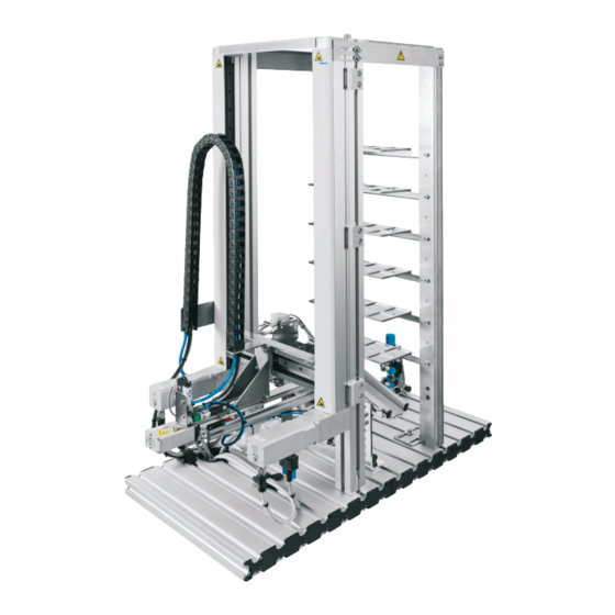
• Werkstücke einzulagern oder • Werkstücke auszulagern 8.2 Ansicht der Station Ansicht der Station Lagern Regallager Profilplatte Wagen mit Motorcontroller Board und SPS EduTrainer ® Universal Baugruppe Zuführ- und Aufnahmeeinheit Modul Erkennen (i-Punkt) Flächenportal mit Spindelachse und pneumatischem Greifer © Festo Didactic 8049748... -
Page 18: Baugruppe Zuführ- Und Aufnahmeeinheit
Lichtschranke eine positive Flanke meldet und • der Reflex-Lichttaster eine positive Flanke meldet Ein silbernes Werkstück wird erkannt wenn: • der induktive Näherungsschalter eine positive Flanke meldet Ein transparentes Werkstück wird erkannt wenn: • die Lichtschranke zwei positive Flanken meldet © Festo Didactic 8049748... -
Page 19: Baugruppe Flächenportal (H-Portal) Mit Spindelachse Und Pneumatischem Greifer
Betriebsmodus Einlagern transportiert das Flächenportal (3) das Werkstück, abhängig vom Messergebnis, zum nächsten freien Fach in der entsprechenden Lagerebene (1). Im Betriebsmodus Auslagern wird das Werkstück nach der Materialanforderung zu einer Nachfolgestation transportiert. Die Linearbewegungen des Flächenportals erledigen elektrische Stellantriebe, die über einen Controller angesteuert werden. © Festo Didactic 8049748... -
Page 20: Baugruppe Regallager
Station Lagern 8.5 Baugruppe Regallager Das Regallager dient zum Speichern/Lagern/Puffern der Werkstücke. In jeder der 6 Lagerebenen können bis zu 8 Werkstücke (in den 4 Farben) abgelegt werden. Es können insgesamt bis zu 48 Werkstücke eingelagert werden. © Festo Didactic 8049748... -
Page 21: Funktion
(schwarz, rot, silbern, transparent), auf einer von 6 Lagerebenen des Regallagers ab. Ein Sensor erkennt in die Aufnahmeeinheit eingelegte Werkstücke und steuert den weiteren Prozessverlauf. Alternativ kann mit einer Bitkombination die Einlagerungsebene oder die Einlagerungsfarbe vorgegeben werden. © Festo Didactic 8049748... -
Page 22: Auslagern
3. Der Greifer wird geschlossen. 4. Abhängig von der erkannten Farbe wird das Werkstück auf eine freie Position in der zugewiesenen Lagerebene transportiert. 5. Der Greifer wird geöffnet. 6. Das Flächenportal und die Spindelachse fahren in die Startposition. © Festo Didactic 8049748... -
Page 23: Inbetriebnahme
SPS Board mit 16 digitalen Ein- und Ausgängen • ein Netzgerät 24 V DC, 4,5 A • eine Druckluftversorgung mit 600 kPa (6 bar) • einen PC mit installierter SPS Programmiersoftware • zwei E/A-Kabel (SysLink) © Festo Didactic 8049748... -
Page 24: Spindelachse Mit Pneumatischem Greifer Am H-Portal Montieren
Halterung an der Traverse Spindelachse mit pneumatischem Greifer und Haltewinkel Scheibe A4,3 (2x) Zylinderschraube M 4x8 (2x) Die Spindelachse mit pneumatischem Greifer und Haltewinkel (2) mit 2 Zylinderschrauben (4) und Scheiben (3) an der Halterung der Traverse (1) befestigen. © Festo Didactic 8049748... -
Page 25: Montage Von Profilplatte Und Bedienpult
Buchse B durch ein SysLink Kabel mit der SysLink Buchse des Bedienpults. SPS Board – Netzgerät Stecken Sie die 4 mm Sicherheitsstecker in die Buchsen des Netzgerätes. PC – SPS Verbinden Sie Ihren PC durch ein Programmierkabel mit der SPS. © Festo Didactic 8049748... -
Page 26: Spannungsversorgung
Programmiersoftware beschrieben ist. Aktuelle SPS Programme für verschiedene Steuerungen finden Sie im Internet unter folgender Adresse: www.festo-didactic.com > Service > MPS® Mechatronische Systeme > Stationen 11.7 Teachen der Positionen des Regallagers Beim Teachen werden der Stationssteuerung (SPS) die Koordinaten der Regallager-Plätze eingelernt (ist im Lieferzustand bereits eingerichtet). - Page 27 9. Das Werkstück vorsichtig, bündig im Lagerfach platzieren (erste Lagerendposition). 10. Die Position speichern („Teach“- Button). 11. Den Greifer öffnen und wieder einfahren. 12. Die Taste „Stop“ am Bedienpult 5 Sekunden gedrückt halten, um die Station zurückzusetzen. 13. Referenzfahrt wiederholen. Das Teachen ist damit abgeschlossen. © Festo Didactic 8049748...
-
Page 28: Ablauf Starten
Folgende Voraussetzungen müssen hergestellt sein: • Sichtprüfung durchgeführt • Funktion der Schutzeinrichtungen geprüft Vorsicht Sollten Schäden festgestellt werden, kann im Betrieb eine Verletzungsgefahr entstehen. Störungen, die die Sicherheit beeinträchtigen können, müssen umgehend dem Fachpersonal mitgeteilt und beseitigt werden! © Festo Didactic 8049748... - Page 29 Pneumatischer Greifer in Stellung Startposition Pneumatischer Greifer innerhalb des Regalbereichs, es besteht Kollisionsgefahr. • Spannungsversorgung angeschlossen und eingeschaltet • Steuerleitungen der Schrittmotoren angeschlossen • Druckluftversorgung angeschlossen und eingeschaltet Sind alle Startvoraussetzungen erfüllt, leuchtet die rote Reset LED am Bedienpult. © Festo Didactic 8049748...
-
Page 30: Automatikbetrieb Starten
Fährt das Flächenportal bei der Referenzfahrt mit dem Greifer nicht automatisch an den obersten rechten Punkt seiner Begrenzungen, so muss die Referenzfahrt wiederholt werden (Taste „Reset“ drücken). Ist keine Wiederholung möglich, so legen Sie die Station still und kontaktieren bitte den Kundendienst. © Festo Didactic 8049748... -
Page 31: Wartung Und Pflege
Es dürfen keine aggressiven oder scheuernden Reinigungsmittel verwendet werden. 13 Weitere Informationen und Aktualisierungen Weiter Informationen und Aktualisierungen zur Technischen Dokumentation der MPS ® Stationen finden Sie im Internet unter der Adresse: www.festo-didactic.com > Service > MPS® Mechatronische Systeme © Festo Didactic 8049748... -
Page 32: Abbildungen Der Warnschilder
Station Lagern 14 Abbildungen der Warnschilder Warnschild: Warnung vor einer Gefahr Warnschild: Warnung vor heißer Oberfläche Warnschild: Warnung vor Quetschgefahr der Hand © Festo Didactic 8049748... - Page 33 Planar surface gantry assembly with spindle axis and pneumatic gripper _____________________ 49 High-bay racking system assembly _____________________________________________________ 50 Function ___________________________________________________________________________ 51 Possible expansions _________________________________________________________________ 51 Possible types of control _____________________________________________________________ 51 Store ______________________________________________________________________________ 51 Issue ______________________________________________________________________________ 52 Sequence description _______________________________________________________________ 52 © Festo Didactic 8049748...
- Page 34 Teaching in the locations of the high-bay racking system __________________________________ 56 11.8 Starting the sequence _______________________________________________________________ 58 11.8.1 Start-up prerequisites _______________________________________________________________ 58 11.8.2 Starting automatic operation __________________________________________________________ 60 Maintenance and care _______________________________________________________________ 61 Further information and updates ______________________________________________________ 61 Illustrations of warning signs _________________________________________________________ 62 © Festo Didactic 8049748...
-
Page 35: General Prerequisites For Operating The Devices
Damaged devices must be barred from further use and removed from the laboratory or classroom. – Damaged connecting cables, pneumatic tubing, and hydraulic hoses represent a safety risk and must be removed from the laboratory or classroom. © Festo Didactic 8049748... -
Page 36: Danger Categories
Indicates a possibly hazardous situation which may result in moderate or slight personal injury if not avoided. Caution Reference to possible property damage: Indicates a possibly hazardous situation which may result in property damage and damage to the environment if not avoided. Note © Festo Didactic 8049748... -
Page 37: Use For Intended Purpose
Festo Didactic hereby excludes any and all liability for damages suffered by trainees, the training company and/or any third parties, which occur during use of the equipment sets in situations which serve any purpose other than training and/or vocational education, unless such damages have been caused by Festo Didactic due to malicious intent or gross negligence. -
Page 38: For Your Safety
Nevertheless, life and limb of the user and third parties may be endangered, and the machine or other property may be damaged during its use. © Festo Didactic 8049748... -
Page 39: Residual Risks And Protective Devices
If they do not function correctly or are missing, they must be repaired or replaced before commissioning. Sticker: Warning concerning a hazard Sticker: Warning concerning danger of pinching the hand Sticker: Warning concerning a hot surface © Festo Didactic 8049748... -
Page 40: Work And Safety Instructions
Use a tool to actuate the limit switches, for example a screwdriver. • Set all components up so that activation of switches and disconnectors is not made difficult. • Follow to the instructions regarding positioning of the components. © Festo Didactic 8049748... - Page 41 • The device is not equipped with an integrated fuse unless specified otherwise in the technical data. • Always pull on the plug when disconnecting connecting cables; never pull the cable. © Festo Didactic 8049748...
- Page 42 Noise caused by escaping compressed air may damage your hearing. Reduce noise by using silencers, or wear hearing protection if noise cannot be avoided. – All of the exhaust ports of the components included in the equipment set are equipped with silencers. Do not remove these silencers. © Festo Didactic 8049748...
-
Page 43: Technical Data
Compressed air consumption at 600 kPa (continuous cycle) 3 l/min Dimensions 350 x 700 x 905 mm Overall height with carrier 1654 mm Workpiece size, 40 mm max. possible edge length or diameter Subject to change © Festo Didactic 8049748... -
Page 44: Pin Allocation Table
21+22 White-pink 24 V power supply for inputs GND A Brown-pink 0 V power supply for outputs GND A Purple 0 V power supply for outputs GND B 23+24 White-blue 0 V power supply for inputs © Festo Didactic 8049748... -
Page 45: Transport, Unpacking, Scope Of Delivery
Examine the station for possible damage after unpacking. The freight forwarder and Festo Didactic must be notified of any damage without delay. 7.3 Scope of delivery Check delivered items against the delivery note and the purchase order. Festo Didactic must be notified of any discrepancies without delay. © Festo Didactic 8049748... -
Page 46: Design
Storage station 8 Design 8.1 The storage station The storage station combines detect and store handling functions. It can be used in an overall sequence as either a receiving or an issuing storage area. © Festo Didactic 8049748... -
Page 47: View Of The Station
View of the storage station High-bay racking system Profile plate Trolley with motor controller board and SPS EduTrainer Universal ® Feed and holding unit assembly Detection module (i-point) Planar surface gantry with spindle axis and pneumatic gripper © Festo Didactic 8049748... -
Page 48: Feed And Holding Unit Assembly
The diffuse sensor indicates a rising edge A silver workpiece is detected when: • The inductive proximity sensor indicates a rising edge A transparent workpiece is detected when: • The through-beam sensor indicates two rising edges © Festo Didactic 8049748... -
Page 49: Planar Surface Gantry Assembly With Spindle Axis And Pneumatic Gripper
(1) depending on the measurement results. In the Issue operating mode, the workpiece is transported to a downstream station upon receipt of a material requisition. Linear motion of the planar surface gantry is driven by electric positioners which are operated by a controller. © Festo Didactic 8049748... -
Page 50: High-Bay Racking System Assembly
8.5 High-bay racking system assembly The high-bay racking system is used to store/buffer workpieces. Up to 8 workpieces (in 4 colors) can be stored on each of the 6 storage levels. A total of 48 workpieces can be stored. © Festo Didactic 8049748... -
Page 51: Function
6 storage levels depending on color (black, red, sliver or transparent). A sensor detects workpieces in the holding unit and controls the remaining process steps. Alternatively, the storage level or the storage color can be specified by means of a bit combination. © Festo Didactic 8049748... -
Page 52: Issue
4. Depending on which color has been detected, the workpiece is advanced to an empty location on the assigned storage level. 5. The gripper is opened. 6. The planar surface gantry and the spindle axis return to the start position. © Festo Didactic 8049748... -
Page 53: Commissioning
A PLC board with 16 digital inputs and outputs • A power supply unit: 24 V DC, 4.5 A • Compressed air supply: 600 kPa (6 bar) • A PC with installed PLC programming software • Two I/O cables (SysLink) © Festo Didactic 8049748... -
Page 54: Mounting The Spindle Axis With Pneumatic Gripper To The Planar Surface Gantry
Spindle axis with pneumatic gripper and mounting bracket Two A4.3 washers Two M 4x8 socket head screws Secure the spindle axis with pneumatic gripper and mounting bracket (2) to the cross-beam retainer (1) with two socket head screws (4) and washers (3). © Festo Didactic 8049748... -
Page 55: Mounting The Profile Plate And The Control Console
B to the SysLink socket on the control console. PLC board to power supply unit Insert the 4 mm safety plugs into the sockets on the power supply unit. PC to PLC Connect your PC to the PLC via a programming cable. © Festo Didactic 8049748... -
Page 56: Power Supply
Current PLC programs for various controllers can be found on the Internet at the following website: www.festo-didactic.com > Services > MPS® The Modular Production System > Stations 11.7 Teaching in the locations of the high-bay racking system During teach-in, the coordinates of the racking system locations are taught in to the station controller (PLC) (already set up upon shipment from the factory). - Page 57 9. Save the position by clicking the “Teach” button. 10. Open the gripper and retract it. 11. Press and hold the “Stop” key on the control console for 5 seconds in order to reset the station. 12. Repeat homing. Teach-in has now been completed. © Festo Didactic 8049748...
-
Page 58: Starting The Sequence
Visual inspection completed • Protective devices tested for correct functioning Caution If any damage is detected, danger of injury may occur during operation. Malfunctions which may impair safety must be reported to appropriately trained personnel and eliminated immediately! © Festo Didactic 8049748... - Page 59 Supply power connected and switched on • Stepper motor control cables connected • Compressed air supply connected and activated After all start-up prerequisites have been fulfilled, the red reset LED lights up at the control console. © Festo Didactic 8049748...
-
Page 60: Starting Automatic Operation
If the planar surface gantry doesn’t automatically travel to the uppermost right-hand point within its limitations with the gripper during homing, homing must be repeated (Press the “Reset” key). If it’s not possible to repeat homing, remove the station from operation and contact customer service. © Festo Didactic 8049748... -
Page 61: Maintenance And Care
Do not use aggressive or abrasive cleaning agents. 13 Further information and updates Further information and updates of the technical documentation for the MPS stations is available on the following website: www.festo-didactic.com > Services > MPS® The Modular Production System © Festo Didactic 8049748... -
Page 62: Illustrations Of Warning Signs
Storage station 14 Illustrations of warning signs Warning concerning a hazard Warning concerning hot surfaces Warning concerning danger of pinching the hand © Festo Didactic 8049748... - Page 63 Subconjunto de estantería de almacenamiento __________________________________________ 80 Funcionamiento ____________________________________________________________________ 81 Posibles ampliaciones _______________________________________________________________ 81 Posibles formas de control ____________________________________________________________ 81 Entrada en almacén _________________________________________________________________ 81 Salida de almacén ___________________________________________________________________ 82 Descripción de las secuencias ________________________________________________________ 82 © Festo Didactic 8049748...
- Page 64 Inicio de la secuencia ________________________________________________________________ 88 11.8.1 Condiciones previas para el inicio ______________________________________________________ 88 11.8.2 Inicio del modo automático ___________________________________________________________ 90 Cuidados y mantenimiento ___________________________________________________________ 91 Informaciones complementarias y actualizaciones _______________________________________ 91 Imágenes de los carteles de advertencia _______________________________________________ 92 © Festo Didactic 8049748...
-
Page 65: Condiciones Generales Para El Uso De Los Equipos
Los aparatos defectuosos deberán inhabilitarse y retirarse de la zona de trabajo. – Los cables y los tubos flexibles para sistemas neumáticos o hidráulicos dañados representan un peligro y deben retirarse del laboratorio o del aula de clases. © Festo Didactic 8049748... -
Page 66: Categorías De Riesgo
Atención Indicaciones que se refieren a posibles daños materiales: ... indica que existe un posible peligro, que puede causar daños materiales y ecológicos si no se adoptan las medidas necesarias para evitarlo. Advertencia © Festo Didactic 8049748... -
Page 67: Uso Previsto
El sistema para la enseñanza de Festo Didactic ha sido concebido exclusivamente para la formación y el perfeccionamiento profesional en materia de sistemas y técnicas de automatización industrial. La empresa u organismo encargado de impartir las clases y/o los instructores deben velar por que los alumnos/aprendices respeten las indicaciones de seguridad que se describen en el presente manual. -
Page 68: Indicaciones De Seguridad
A pesar de ello, su utilización puede generar peligros que podrían afectar la integridad física o poner en peligro la vida de los usuarios o de terceros, así como también provocar daños en la máquina u otros daños materiales. © Festo Didactic 8049748... -
Page 69: Peligros Restantes Y Sistemas De Protección
Si no funcionasen correctamenteo o si no existiesen, deberán repararse o colocarse antes de la puesta en funcionamiento. Etiqueta: advertencia sobre un peligro Etiqueta: advertencia de peligro de aprisionamiento de la mano Etiqueta: advertencia de superficie caliente © Festo Didactic 8049748... -
Page 70: Instrucciones De Seguridad Y Utilización
(por ejemplo, un destornillador). • Efectúe el montaje de todos los componentes de tal manera que pueda acceder fácilmente a los interruptores y a las conexiones. • Respete las indicaciones sobre el posicionamiento de los componentes. © Festo Didactic 8049748... - Page 71 • Si no se indica lo contrario en los datos técnicos, el aparato no contiene un fusible integrado. • Al desconectar los cables, tire únicamente de los conectores de seguridad, nunca de los cables. © Festo Didactic 8049748...
- Page 72 Reduzca el nivel de ruidos Utilizando silenciadores, o bien tapones para los oídos si no fuese posible evitar los ruidos. – Todas las conexiones de escape de aire deberán estar provistos de silenciadores. No retire esos silenciadores. © Festo Didactic 8049748...
-
Page 73: Especificaciones Técnicas
Consumo de aire comprimido con 600 kPa (ciclo continuo) 3 l/min Dimensiones 350 mm x 700 mm x 905 mm Altura total con carro 1654 mm Tamaño de la pieza, 40 mm longitud / diámetro máximos admisibles Reservado el derecho de modificación © Festo Didactic 8049748... -
Page 74: Tabla De Ocupación De Contactos
Alimentación de 0 V en las salidas GND B 23+24 Blanco y azul Alimentación de 0 V en las entradas Nota En todas las variantes de PLC, los cables que puentean la parada de emergencia están conectados a bit 1.5. © Festo Didactic 8049748... -
Page 75: Transporte / Desembalaje / Dotación Del Suministro
La caja deberá moverse únicamente utilizando una carretilla elevadora apropiada. La caja deberá estar asegurada de tal manera que no pueda caerse. Cualquier daño ocurrido durante el transporte deberá notificarse de inmediato al transportista y a Festo Didactic. 7.2 Desembalaje Para sacar la estación de su caja de transporte, deberá... -
Page 76: Estructura
Estación de almacenamiento 8 Estructura 8.1 La estación de almacenamiento La estación de almacenamiento combina las funciones de manipulación consistentes en almacenar y detectar piezas. La estación de almacenamiento puede incluirse como almacén de entrada o de salida. © Festo Didactic 8049748... -
Page 77: Vista De La Estación
Placa perfilada Carro con placa de controlador de motor y SPS EduTrainer Universal ® Subconjunto alimentación y recepción Módulo de detección (punto i) Pórtico horizontal de dos ejes con eje accionado por husillo y pinza neumática © Festo Didactic 8049748... -
Page 78: Subconjunto De Alimentación Y Recepción
Una pieza de color plateado se reconoce si se cumplen las siguientes condiciones: • el sensor de proximidad inductivo confirma un flanco positivo Una pieza transparente se reconoce si se cumplen las siguientes condiciones: • La barrera de luz confirma dos flanco positivos © Festo Didactic 8049748... -
Page 79: Subconjunto De Pórtico Horizontal De Dos Ejes (H-Portal) Con Eje Accionado Por Husillo Y Pinza Neumática
(1). En el modo de funcionamiento de salida de almacén, la pieza a manipular se transporta a una estación siguiente en función del material solicitado. Los movimientos lineales del pórtico horizontal de dos ejes están a cargo de actuadores eléctricos, controlados por un controlador. © Festo Didactic 8049748... -
Page 80: Subconjunto De Estantería De Almacenamiento
El subconjunto de estanterías sirve para almacenar (temporalmente) las piezas a manipular. En cada uno de los seis niveles pueden colocarse hasta ocho piezas (de cualquiera de los cuatro colores). En total, pueden almacenarse 48 piezas. © Festo Didactic 8049748... -
Page 81: Funcionamiento
(negro, rojo, plateado, transparente). Un sensor detecta las piezas a manipular insertadas en el unidad de recepción y controla el proceso posterior. De forma alternativa, puede determinarse el nivel de almacenamiento de entrada o el color del almacenamiento de entrada mediante una combinación de bits. © Festo Didactic 8049748... -
Page 82: Salida De Almacén
4. En función del color detectado, la pieza a manipular se transporta en una posición libre al nivel de almacenamiento correspondiente. 5. Las pinzas se abren. 6. El pórtico horizontal de dos ejes y el eje accionado por husillo de la pinza se desplazan a la posición inicial. © Festo Didactic 8049748... -
Page 83: Puesta A Punto
Una placa PLC con 16 entradas y salidas digitales • Una unidad de alimentaciónde 24 V DC, 4,5 A • Una alimentación de aire comprimido con 600 kPa (6 bar) • Un PC con software de programación PLC instalado • Dos cables E/S (SysLink) © Festo Didactic 8049748... -
Page 84: Montaje Del Eje Accionado Por Husillo Con Pinza Neumática En El Pórtico Horizontal De Dos Ejes
Arandela A4,3 (2x) Tornillo cilíndrico M 4x8 (2x) Fijar el eje accionado por husillo con pinza neumática y escuadra de fijación (2) mediante 2 tornillos cilíndricos (4) y arandelas (3) a la sujeción del travesaño (1). © Festo Didactic 8049748... -
Page 85: Montaje De La Placa Perfilada Y Del Panel De Mando
Placa PLC – Unidad de alimentación eléctrica Conecte los conectores de seguridad de 4 mm a los conectores de la unidad de alimentación. PC – PLC Conecte el PC al PLC mediante un cable de programación. © Festo Didactic 8049748... -
Page 86: Fuente De Alimentación
En la dirección Internet que se indica a continuación encontrará programas PLC modernos para diversos tipos de unidades de control: www.festo-didactic.com > Asistencia técnica> MPS® Sistemas mecatrónicos > Estaciones 11.7 Programación por teach-in de las posiciones de la estantería En caso de programación por teach-in, las coordenadas de los huecos de las estanterías se memorizan en el sistema de control de estaciones (PLC) (ya ajustado en estado de suministro). - Page 87 11. Abrir la pinza y hacerla retroceder. 12. Mantener pulsada la tecla "Parada" del panel de mando durante 5 segundos para reiniciar la estación. 13. Repetir el recorrido de referencia. De esta forma, la programación de teach-in debe estar completa. © Festo Didactic 8049748...
-
Page 88: Inicio De La Secuencia
Comprobación del funcionamiento de los dispositivos de protección Atención Si se presentan daños, puede existir peligro de lesiones durante el servicio. Las anomalías que puedan comprometer la seguridad deben notificarse inmediatamente al personal técnico y eliminarse a la mayor brevedad. © Festo Didactic 8049748... - Page 89 Las líneas de control de los motores paso a paso están conectadas • La alimentación de aire comprimido está conectada y activada Si se cumplen todas las condiciones previas para el inicio, se enciende el LED rojo de reset en el panel de mando. © Festo Didactic 8049748...
-
Page 90: Inicio Del Modo Automático
(presionar la tecla "Reset"). Si no es posible repetirlo, detenga la estación y póngase en contacto con el servicio al cliente. © Festo Didactic 8049748... -
Page 91: Cuidados Y Mantenimiento
En la dirección Internet que se indica a continuación se ofrecen informaciones complementarias y actualizaciones de la documentación técnica de las estaciones MPS www.festo-didactic.com > Servicio y Asistencia > MPS® Sistema de Producción Modular > Estaciones © Festo Didactic 8049748... -
Page 92: Imágenes De Los Carteles De Advertencia
Estación de almacenamiento 14 Imágenes de los carteles de advertencia Advertencia sobre un peligro Advertencia de superficie caliente Advertencia de peligro de aprisionamiento de la mano © Festo Didactic 8049748... - Page 93 Sous-ensemble Portique bidimensionnel avec axe à vis et pince pneumatique________________ 109 Sous-ensemble Magasin ____________________________________________________________ 110 Fonctionnement ___________________________________________________________________ 111 Extensions possibles _______________________________________________________________ 111 Types de commande possibles _______________________________________________________ 111 Stockage _________________________________________________________________________ 111 Déstockage _______________________________________________________________________ 112 Description du cycle ________________________________________________________________ 112 © Festo Didactic 8049748...
- Page 94 Démarrage du cycle ________________________________________________________________ 118 11.8.1 Conditions préalables au démarrage __________________________________________________ 118 11.8.2 Démarrage du mode automatique ____________________________________________________ 120 Maintenance et entretien ___________________________________________________________ 121 Informations complémentaires et mises à jour _________________________________________ 121 Panneaux d'avertissement __________________________________________________________ 122 © Festo Didactic 8049748...
-
Page 95: Conditions Générales D'exploitation Des Appareils
Les appareils endommagés doivent être interdits d'utilisation et retirés du laboratoire ou de la salle de TP. – Les câbles de connexion, tuyaux d'air comprimé et hydrauliques endommagés présentent un risque pour la sécurité et doivent être retirés du laboratoire ou de la salle de TP. © Festo Didactic 8049748... -
Page 96: Catégories De Dangers
évitée. Attention Signalement de dommages matériels potentiels : … signale une situation potentiellement dangereuse qui peut causer des dommages matériels et environnementaux si elle n'est pas évitée. Nota © Festo Didactic 8049748... -
Page 97: Usage Normal
Le système de formation de Festo Didactic est exclusivement destiné à la formation initiale et continue dans le domaine de l’automatisation et de la technique. Il incombe à l’établissement de formation et/ou aux formateurs de faire respecter par les étudiants les consignes de sécurité... -
Page 98: Pour Votre Sécurité
Son utilisation peut néanmoins mettre en danger la vie et la santé de l’utilisateur ou de tiers ainsi qu’affecter l’intégrité de la machine ou d’autres biens. © Festo Didactic 8049748... -
Page 99: Dangers Résiduels Et Dispositifs De Protection
S'ils ne fonctionnent pas correctement ou s'ils manquent, réparez ou remplacez-les avant la mise en service. Autocollant : alerte de danger Autocollant : alerte de danger d’écrasement de la main Autocollant : alerte de surface chaude © Festo Didactic 8049748... -
Page 100: Instructions Et Consignes De Sécurité
Utilisez un outil, par exemple un tournevis, pour actionner les capteurs de fin de course. • Installez les composants de telle sorte qu'ils ne gênent pas l'actionnement d'interrupteurs ni de dispositifs de sectionnement de l'alimentation. • Notez les indications concernant l'implantation des composants. © Festo Didactic 8049748... - Page 101 • Sauf indications contraires dans les caractéristiques techniques, l'appareil ne possède pas de fusible intégré. • Pour débrancher les câbles de liaison, tirez sur les connecteurs, pas sur les câbles. © Festo Didactic 8049748...
- Page 102 Le bruit produit par l'échappement d'air comprimé peut nuire à l'ouïe. Réduisez le bruit en utilisant des silencieux ou portez un casque anti-bruit si le bruit est inévitable. – Équipez tous les orifices d'échappement des jeux d'équipement de silencieux. Ne retirez pas ces silencieux. © Festo Didactic 8049748...
-
Page 103: Caractéristiques Techniques
Consommation d'air comprimé sous 600 kPa (cycle permanent) 3 l/min Dimensions 350 mm x 700 mm x 905 mm Hauteur totale du chariot 1654 mm Taille des pièces, 40 mm longueur d'arête/diamètre max. possible Sous réserve de modifications © Festo Didactic 8049748... -
Page 104: Brochage
Alimentation 0 V des sorties GND A lilas Alimentation 0 V des sorties GND B 23+24 blanc/bleu Alimentation 0 V des entrées Nota Sur toutes les variantes préférentielles d'API, des cavaliers sont enfichés entre ARRÊT D’URGENCE et le bit 1.5. © Festo Didactic 8049748... -
Page 105: Transport/Déballage/Fourniture
La caisse doit être exclusivement manutentionnée au moyen de transpalettes ou de chariots à fourche appropriés. Il convient de faire en sorte que la caisse ne puisse se renverser ni tomber. Tout dommage dû au transport doit être immédiatement signalé au transporteur et à Festo Didactic. 7.2 Déballage Au déballage de la station, retirez avec précaution le matériau de calage de la caisse. -
Page 106: Présentation
Station de stockage 8 Présentation 8.1 La station de stockage La station de stockage combine les fonctions d'emmagasinage et de détection. Elle peut être utilisée dans un cycle complet comme entrepôt d'entrée ou de sortie. © Festo Didactic 8049748... -
Page 107: Vue De La Station
Vue de la station de stockage Magasin Plaque profilée Chariot avec carte contrôleur de moteur et API EduTrainer ® Universal Unité d’amenage et de réception Module de détection (point i) Portique bidimensionnel avec axe à vis et pince pneumatique © Festo Didactic 8049748... -
Page 108: Sous-Ensemble Unité D'amenage Et De Réception
à réflexion transmet un front positif. Une pièce argentée est détectée lorsque : • le capteur de proximité inductif transmet un front positif. Une pièce transparente est détectée lorsque : • la barrière lumineuse transmet deux fronts positifs. © Festo Didactic 8049748... -
Page 109: Sous-Ensemble Portique Bidimensionnel Avec Axe À Vis Et Pince Pneumatique
(1). En mode Déstockage, la pièce est transportée sur demande vers une station en aval. Les mouvements linéaires du portique sont exécutés par des actionneurs électriques, commandés par un contrôleur. © Festo Didactic 8049748... -
Page 110: Sous-Ensemble Magasin
8.5 Sous-ensemble Magasin Le magasin sert à l'emmagasinage et au stockage temporaire des pièces. Chacun des 6 niveaux de stockage permet d'entreposer jusqu'à 8 pièces (dans les 4 couleurs). On peut stocker au total 48 pièces. © Festo Didactic 8049748... -
Page 111: Fonctionnement
(noir, rouge, argenté, transparent), à l'un des 6 niveaux de stockage du magasin. Un capteur identifie les pièces déposées dans l’unité de réception et pilote la poursuite du cycle. Une alternative est d’utiliser une combinaison binaire pour spécifier le niveau ou la couleur de stockage. © Festo Didactic 8049748... -
Page 112: Déstockage
4. Suivant la couleur détectée, la pièce est alors acheminée à un emplacement libre du niveau de stockage adéquat. 5. La pince s’ouvre. 6. Le portique et l’axe à vis de la pince reviennent en position de départ. © Festo Didactic 8049748... -
Page 113: Mise En Service
24 V CC, 4,5 A, • une alimentation en air comprimé à 600 kPa (6 bar), • un PC sur lequel est installé un logiciel de programmation d’API et • deux câbles d’E/S (SysLink). © Festo Didactic 8049748... -
Page 114: Montage De L'axe À Vis Avec Pince Pneumatique Sur Le Portique
Rondelle A4,3 (2x) Vis à tête cylindrique M 4x8 (2x) Fixer l’axe à vis avec pince pneumatique et équerre-support (2) par 2 vis à tête cylindrique (4) et rondelles (3) au support de la traverse (1). © Festo Didactic 8049748... -
Page 115: Montage De La Plaque Profilée Et Du Pupitre De Commande
Carte API – Bloc d’alimentation Reliez les fiches de sécurité de 4 mm aux douilles du bloc d'alimentation. PC – API Reliez votre PC à l'API par un câble de programmation. © Festo Didactic 8049748... -
Page 116: Alimentation Électrique
Vous trouverez les programmes API actuels pour différents automates sur Internet, à l'adresse suivante : www.festo-didactic.com > Service > Systèmes mécatroniques MPS® > Stations 11.7 Apprentissage des positions du magasin L’apprentissage consiste à apprendre à la commande de la station (API) les coordonnées des emplacements de stockage dans le magasin (déjà... - Page 117 10. Enregistrer la position (bouton « Teach »). 11. Ouvrir la pince et la rentrer. 12. Appuyer 5 secondes sur la touche « Stop » au pupitre de commande pour réinitialiser la station. 13. Répéter le référencement. L’apprentissage est ainsi terminé. © Festo Didactic 8049748...
-
Page 118: Démarrage Du Cycle
Bon fonctionnement des dispositifs de protection vérifié Attention Les dommages éventuellement constatés peuvent à l’origine de blessures en service. Les dysfonctionnements susceptibles d’affecter la sécurité doivent être immédiatement signalés au personnel spécialisé et être éliminés ! © Festo Didactic 8049748... - Page 119 Les câbles de commande des moteurs pas à pas sont raccordés. • L’alimentation en air comprimé est raccordée et sous pression. Quand toutes les conditions préalables au démarrage sont remplies, la LED Reset rouge s’allume au pupitre de commande. © Festo Didactic 8049748...
-
Page 120: Démarrage Du Mode Automatique
Si, lors du référencement, le portique, avec sa pince, ne rallie pas automatiquement le point droit le plus haut de ses limitations, le référencement doit être répété (appuyer sur la touche « Reset »). S’il est impossible de répéter le référencement, immobilisez la station et contactez le service après- vente. © Festo Didactic 8049748... -
Page 121: Maintenance Et Entretien
13 Informations complémentaires et mises à jour La documentation technique des stations MPS fait l’objet d’informations complémentaires et mises à jour ® que vous trouverez sur Internet à l’adresse : www.festo-didactic.com > Service > Systèmes mécatroniques MPS ® © Festo Didactic 8049748... -
Page 122: Panneaux D'avertissement
Station de stockage 14 Panneaux d'avertissement Panneau d'avertissement : alerte de danger Panneau d'avertissement : alerte de surface chaude Panneau d'avertissement : alerte de danger d’écrasement de la main © Festo Didactic 8049748... - Page 124 Festo Didactic SE Rechbergstraße 3 73770 Denkendorf Germany +49 711 3467-0 www.festo-didactic.com +49 711 34754-88500 did@festo.com...
Need help?
Do you have a question about the MPS 8049013 and is the answer not in the manual?
Questions and answers