
Related Manuals for Festo MPS 8034567


Summary of Contents for Festo MPS 8034567
- Page 1 8034567 Pick&Place station ® Kurzanleitung Quick Start Guide Instrucciones breves Prise en main Festo Didactic 8034663 de/en/es/fr 11/2016 R1.1...
- Page 2 Revision level: 10/2016 Authors: Frank Ebel, Mustafa Ersoy Layout: 11/2016, Frank Ebel © Festo Didactic SE, Rechbergstraße 3, 73770 Denkendorf, Germany, 2016 +49 711 3467-0 www.festo-didactic.com +49 711 34754-88500 did@festo.com Weitergabe sowie Vervielfältigung dieses Dokuments, Verwertung und Mitteilung seines Inhalts verboten, soweit nicht ausdrücklich gestattet.
-
Page 3: Table Of Contents
Ablaufbeschreibung _________________________________________________________________ 17 Inbetriebnahme ____________________________________________________________________ 18 10.1 Arbeitsplatz ________________________________________________________________________ 18 10.2 Montage von Profilplatte und Bedienpult ________________________________________________ 19 10.3 Kabelverbindungen __________________________________________________________________ 19 10.4 Spannungsversorgung _______________________________________________________________ 20 10.5 SPS Programme laden _______________________________________________________________ 20 10.6 Ablauf starten ______________________________________________________________________ 20 © Festo Didactic 8034663... - Page 4 Inhalt Wartung und Pflege _________________________________________________________________ 21 Weitere Informationen und Aktualisierungen ___________________________________________ 21 © Festo Didactic 8034663...
-
Page 5: Allgemeine Voraussetzungen Zum Betreiben Der Geräte
Es dürfen keine Geräte mit Schäden oder Mängeln verwendet werden. – Schadhafte Geräte sind zu sperren und aus dem Labor- oder Unterrichtsraum zu entnehmen. – Beschädigte Verbindungsleitungen, Druckluftschläuche und Hydraulikschläuche stellen ein Sicherheitsrisiko dar und müssen aus dem Labor- oder Unterrichtsraum entfernt werden. © Festo Didactic 8034663... -
Page 6: Piktogramme
Regeln gebaut. Dennoch können bei unsachgemäßer Verwendung Gefahren für Leib und Leben des Benutzers oder Dritter und Beeinträchtigungen der Komponenten entstehen. Das Lernsystem von Festo Didactic ist ausschließlich für die Aus- und Weiterbildung im Bereich Automatisierung und Technik entwickelt und hergestellt. Das Ausbildungsunternehmen und/oder die Ausbildenden hat/haben dafür Sorge zu tragen, dass die Auszubildenden die Sicherheitsvorkehrungen, die... -
Page 7: Für Ihre Sicherheit
Stand der Technik und den anerkannten sicherheitstechnischen Regeln gebaut. Dennoch können bei ihrer Verwendung Gefahren für Leib und Leben des Benutzers oder Dritter bzw. Beeinträchtigungen an der Maschine oder an anderen Sachwerten entstehen. © Festo Didactic 8034663... -
Page 8: Sicher Arbeiten
Benutzen Sie zur Betätigung der Grenztaster ein Werkzeug, z. B. einen Schraubendreher. • Stellen Sie alle Komponenten so auf, dass das Betätigen von Schaltern und Trenneinrichtungen nicht erschwert wird. • Beachten Sie Angaben zur Platzierung der Komponenten. © Festo Didactic 8034663... - Page 9 Einige Geräte haben einen hohen Ableitstrom. Diese Geräte müssen zusätzlich mit einem Schutzleiter geerdet werden. • Wenn in den Technischen Daten nicht anders angegeben, besitzt das Gerät keine integrierte Sicherung. • Ziehen Sie beim Abbauen der Verbindungsleitungen nur an den Sicherheitssteckern, nicht an den Leitungen. © Festo Didactic 8034663...
- Page 10 Lärm durch ausströmende Druckluft kann schädlich für das Gehör sein. Reduzieren Sie den Lärm durch den Einsatz von Schalldämpfern oder tragen Sie einen Gehörschutz, falls der Lärm sich nicht vermeiden lässt. – Alle Abluftanschlüsse der Komponenten der Gerätesätze sind mit Schalldämpfern versehen. Entfernen Sie diese Schalldämpfer nicht. © Festo Didactic 8034663...
-
Page 11: Technische Daten
Ausgänge: max. 4 A gesamt Elektrischer Anschluss 24-polige IEEE-488 Buchse (SysLink) Pneumatischer Anschluss Kunststoffschlauch mit 6 mm Außendurchmesser Druckluftverbrauch bei 600 kPa (Dauerzyklus) 3 l/min Maße 350 mm x 700 mm x 450 mm Änderungen vorbehalten © Festo Didactic 8034663... -
Page 12: Kontaktbelegungstabelle
24 V Versorgung der Eingänge GND A braun-rosa 0V Versorgung der Ausgänge GND A lila 0V Versorgung der Ausgänge GND B 23+24 weiß-blau 0V Versorgung der Eingänge Hinweis Bei allen Vorzugsvarianten SPS sind Kabelbrücken von NOT-AUS auf Bit 1.5 gesteckt. © Festo Didactic 8034663... -
Page 13: Transport/Auspacken/Lieferumfang
Die Transportbox darf ausschließlich mit geeigneten Hubwagen oder Gabelstaplern transportiert werden. Die Transportbox muss gegen Umfallen und Herunterfallen gesichert sein. Transportschäden sind unverzüglich dem Spediteur und Festo Didactic zu melden. 6.2 Auspacken Beim Auspacken der Station das Füllmaterial der Transportbox vorsichtig entfernen. Beim Auspacken der Station darauf achten, dass keine Aufbauten der Station beschädigt werden. -
Page 14: Aufbau
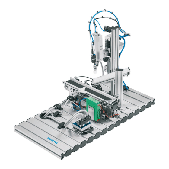
– Fügen – Zusammensetzen – Einlegen ist Einlegen das Fügen, bei dem ein Fügeteil in ein Formelement eines anderen Fügeteils eingelegt wird. Mit der Station Pick&Place wird das Einlegen eines Werkstückeinsatzes in ein Gehäuse realisiert. Als Werkstückeinsätze stehen eine Uhr, ein Thermometer und ein Hygrometer zur Verfügung. © Festo Didactic 8034663... -
Page 15: Das Modul Pick&Place
Vakuumgenerator, Vakuumfilter, Faltenbalg- Saugnapf, Druckschalter, Ventilinsel, Druckregelventil und elektrischer Schnittstelle aufgebaut. Hinweis In einer weiteren Version ist an Stelle des Faltenbalg-Saugnapfs ein Parallelgreifer verbaut. Der Parallelgreifer greift die Werkstücke. Ein Näherungsschalter erfasst, ob der Greifer geschlossen ist. © Festo Didactic 8034663... -
Page 16: Das Modul Band
Bandanfang, vor dem Vereinzeler und am Bandende erfolgt durch optische Näherungsschalter mit Lichtleitern. Der Antrieb des Gurtbandes erfolgt durch einen Gleichstrom-Getriebemotor. Durch einen angebauten Elektromagneten (Drehmagnet) mit Vereinzeler können die Werkstücke gestoppt und vereinzelt werden. Die Endlagen werden mit induktiven Näherungsschaltern nachgewiesen. © Festo Didactic 8034663... -
Page 17: Funktion
3. Ein Werkstückeinsatz wird von der Rutsche geholt und in das Gehäuse eingelegt. 4. Der Bandmotor wird eingeschaltet und der Vereinzeler lässt das Werkstück passieren. 5. Das Werkstück wird zum Bandende transportiert. 6. Am Bandende wird das Werkstück nachgewiesen und der Bandmotor wird ausgeschaltet. © Festo Didactic 8034663... -
Page 18: Inbetriebnahme
SPS Board mit 16 digitalen Ein- und Ausgängen • ein Netzgerät 24 V DC, 4,5 A • eine Druckluftversorgung mit 600 kPa (6 bar) • einen PC mit installierter SPS Programmiersoftware • zwei E/A-Kabel (SysLink) © Festo Didactic 8034663... -
Page 19: Montage Von Profilplatte Und Bedienpult
Kabel mit der SysLink Buchse des Bedienpults. 3. SPS Board – Netzgerät Stecken Sie die 4 mm Sicherheitsstecker in die Buchsen des Netzgerätes. 4. PC – SPS Verbinden Sie Ihren PC durch ein Programmierkabel mit der SPS. © Festo Didactic 8034663... -
Page 20: Spannungsversorgung
Gehen Sie zum Laden der SPS Programme so vor, wie es in den Benutzerhandbüchern der von Ihnen verwendeten Programmiersoftware beschrieben ist. Aktuelle SPS Programme für verschiedene Steuerungen finden Sie im Internet unter folgender Adresse: www.festo-didactic.com > Service > MPS® Mechatronische Systeme > Stationen 10.6 Ablauf starten 1. Überprüfen Sie Spannungsversorgung und Druckluftversorgung. - Page 21 Es dürfen keine aggressiven oder scheuernden Reinigungsmittel verwendet werden. 12 Weitere Informationen und Aktualisierungen Weiter Informationen und Aktualisierungen zur Technischen Dokumentation der MPS Stationen finden Sie im Internet unter der Adresse: www.festo-didactic.com > Service > MPS® Mechatronische Systeme © Festo Didactic 8034663...
- Page 22 Station Pick&Place © Festo Didactic 8034663...
- Page 23 Workstation ________________________________________________________________________ 38 10.2 Mounting the profile plate and the control console ________________________________________ 39 10.3 Cable connections ___________________________________________________________________ 39 10.4 Power supply _______________________________________________________________________ 40 10.5 Loading the PLC program _____________________________________________________________ 40 10.6 Starting the sequence _______________________________________________________________ 40 © Festo Didactic 8034663...
- Page 24 Table of contents Maintenance and care _______________________________________________________________ 41 Further information and updates ______________________________________________________ 41 © Festo Didactic 8034663...
-
Page 25: General Requirements For Operating The Devices
Damaged devices must be barred from further use and removed from the laboratory or classroom. – Damaged connecting cables, pneumatic tubing, and hydraulic hoses represent a safety risk and must be removed from the laboratory or classroom. © Festo Didactic 8034663... -
Page 26: Pictograms
Festo Didactic hereby excludes any and all liability for damages suffered by trainees, the training company and/or any third parties, which occur during use of the equipment sets in situations which serve any purpose other than training and/or vocational education, unless such damages have been caused by Festo Didactic due to malicious intent or gross negligence. -
Page 27: For Your Safety
Nevertheless, life and limb of the user and third parties may be endangered, and the machine or other property may be damaged during its use. © Festo Didactic 8034663... -
Page 28: Working Safely
Use a tool to actuate the limit switches, for example a screwdriver. • Set all components up so that activation of switches and disconnectors is not made difficult. • Follow to the instructions regarding positioning of the components. © Festo Didactic 8034663... - Page 29 • The device is not equipped with an integrated fuse unless specified otherwise in the technical data. • Always pull on the plug when disconnecting connecting cables; never pull the cable. © Festo Didactic 8034663...
- Page 30 Noise caused by escaping compressed air may damage your hearing. Reduce noise by using silencers, or wear hearing protection if noise cannot be avoided. – All of the exhaust ports of the components included in the equipment set are equipped with silencers. Do not remove these silencers. © Festo Didactic 8034663...
-
Page 31: Technical Data
Electrical connection 24-pin IEEE 488 socket (SysLink) Pneumatic connection Plastic tubing with 6 mm outside diameter Compressed air consumption at 600 kPa (continuous cycling) 3 l/min Dimensions 350 x 700 x 450 mm Subject to change © Festo Didactic 8034663... -
Page 32: Pin Allocation Table
0 V power supply for outputs GND A Purple 0 V power supply for outputs GND B 23+24 White-blue 0 V power supply for inputs Note Cable jumpers are connected from emergency off to bit 1.5 on all PLC variants. © Festo Didactic 8034663... -
Page 33: Transport, Unpacking, Scope Of Delivery
Examine the station for possible damage after unpacking. The freight forwarder and Festo Didactic must be notified of any damage without delay. 6.3 Scope of delivery Check delivered items against the delivery note and the purchase order. Festo Didactic must be notified of any discrepancies without delay. © Festo Didactic 8034663... -
Page 34: Layout
The Pick&Place station inserts a workpiece insert into a workpiece housing. The following workpiece inserts are available: a clock, a thermometer and a hygrometer. © Festo Didactic 8034663... -
Page 35: The Pick&Place Module
Note In another version, a parallel gripper is used instead of the bellows suction cup. The workpieces are gripped by a parallel gripper. A proximity sensor detects, if the gripper is closed. © Festo Didactic 8034663... -
Page 36: The Conveyor Module
The conveyor belt is driven by a DC gear motor. The workpieces can be stopped and separated by an attached electromagnet (solenoid) with separator. The end positions are monitored by inductive proximity switches. © Festo Didactic 8034663... -
Page 37: Function
4. The separator is reversed and the conveyor belt motor is switched on. 5. The workpiece is transported to the end of the conveyor belt. 6. The complete workpiece is detected at the end of the conveyor belt. The conveyor belt motor is switched off. © Festo Didactic 8034663... -
Page 38: Commissioning
A PLC board with 16 digital inputs and outputs • A power supply unit: 24 V DC, 4.5 A • Compressed air supply: 600 kPa (6 bar) • A PC with installed PLC programming software • Two I/O cables (SysLink) © Festo Didactic 8034663... -
Page 39: Mounting The Profile Plate And The Control Console
SysLink cable. 3. PLC board to power supply unit Insert the 4 mm safety plug into the socket on the power supply unit. 4. PC to PLC Connect your PC to the PLC via a programming cable. © Festo Didactic 8034663... -
Page 40: Power Supply
Current PLC programs for various controllers can be found on the Internet at the following website: www.festo-didactic.com > Services > MPS® The Modular Production System > Stations 10.6 Starting the sequence 1. Check power supply and compressed air supply. - Page 41 Do not use aggressive or abrasive cleaning agents. 12 Further information and updates Further information and updates of the technical documentation for the MPS stations is available on the following website: www.festo-didactic.com > Services > MPS® The Modular Production System © Festo Didactic 8034663...
- Page 42 Pick&Place station © Festo Didactic 8034663...
- Page 43 Montaje de la placa perfilada y del panel de mando _______________________________________ 59 10.3 Conexiones de cable _________________________________________________________________ 59 10.4 Fuente de alimentación ______________________________________________________________ 60 10.5 Cargar programas PLC _______________________________________________________________ 60 10.6 Inicio de la secuencia ________________________________________________________________ 60 © Festo Didactic 8034663...
- Page 44 Indice Cuidados y mantenimiento ___________________________________________________________ 61 Informaciones complementarias y actualizaciones _______________________________________ 61 © Festo Didactic 8034663...
-
Page 45: Condiciones Generales Para El Uso De Los Equipos
Los aparatos defectuosos deberán inhabilitarse y retirarse de la zona de trabajo. – Los cables y los tubos flexibles para sistemas neumáticos o hidráulicos dañados representan un peligro y deben retirarse del laboratorio o del aula de clases. © Festo Didactic 8034663... -
Page 46: Pictogramas
El sistema para la enseñanza de Festo Didactic ha sido concebido exclusivamente para la formación y el perfeccionamiento profesional en materia de sistemas y técnicas de automatización industrial. La empresa u organismo encargado de impartir las clases y/o los instructores deben velar por que los alumnos/aprendices respeten las indicaciones de seguridad que se describen en el presente manual. -
Page 47: Indicaciones De Seguridad
A pesar de ello, su utilización puede generar peligros que podrían afectar la integridad física o poner en peligro la vida de los usuarios o de terceros, así como también provocar daños en la máquina u otros daños materiales. © Festo Didactic 8034663... -
Page 48: Trabajar Con Seguridad
Para accionar los detectores de posiciones finales, utilice una herramienta (por ejemplo, un destornillador). • Efectúe el montaje de todos los componentes de tal manera que pueda acceder fácilmente a los interruptores y a las conexiones. • Respete las indicaciones sobre el posicionamiento de los componentes. © Festo Didactic 8034663... - Page 49 • Si no se indica lo contrario en los datos técnicos, el aparato no contiene un fusible integrado. • Al desconectar los cables, tire únicamente de los conectores de seguridad, nunca de los cables. © Festo Didactic 8034663...
- Page 50 Reduzca el nivel de ruidos utilizando silenciadores, o bien tapones para los oídos si no fuese posible evitar los ruidos. – Todas las conexiones de escape de aire deberán estar provistos de silenciadores. No retire esos silenciadores. © Festo Didactic 8034663...
-
Page 51: Especificaciones Técnicas
Tubo flexible de material sintético de diámetro exterior Conexión neumática de 6 mm Consumo de aire comprimido con 600 kPa (ciclo continuo) 3 l/min Dimensiones 350 mm x 700 mm x 200 mm Reservado el derecho de modificación © Festo Didactic 8034663... -
Page 52: Tabla De Ocupación De Contactos
Alimentación de 0 V en las salidas GND B 23+24 Blanco y azul Alimentación de 0 V en las entradas Nota En todas las variantes de PLC, los cables que puentean la parada de emergencia están conectados a bit 1.5. © Festo Didactic 8034663... -
Page 53: Transporte / Desembalaje / Dotación Del Suministro
La caja deberá moverse únicamente utilizando una carretilla elevadora apropiada. La caja deberá estar asegurada de tal manera que no pueda caerse. Cualquier daño ocurrido durante el transporte deberá notificarse de inmediato al transportista y a Festo Didactic. 6.2 Desembalaje Para sacar la estación de su caja de transporte, deberá... -
Page 54: Construcción
(enrasar, unir, colocar), insertar significa colocar una pieza en otra en determinada posición. Con la estación Pick&Place se coloca una pieza dentro de un cuerpo. Las piezas para insertar disponibles son un reloj, un termómetro y un higrómetro. © Festo Didactic 8034663... -
Page 55: El Módulo Pick&Place
Notas En otra versión, se usa una pinza paralela en lugar de vacío. La pinza paralela recoge las piezas. Un detector de proximidad registra si la pinza está cerrada. © Festo Didactic 8034663... -
Page 56: Módulo Cinta De Transporte
La cinta se impulsa con un motorreductor DC. Las piezas a manipular pueden detenerse y separarse con una bobina magnética incorporada (electroimán) con separador. Las posiciones finales se detectan con sensores de proximidad inductivos. © Festo Didactic 8034663... -
Page 57: Funcionamiento
4. Se pone en funcionamiento el motor de la cinta y el separador deja pasar la pieza. 5. La pieza se transporta hasta el final de la cinta. 6. Si se detecta la pieza al final de la cinta, se desconecta el motor de la cinta. © Festo Didactic 8034663... -
Page 58: Puesta A Punto
• Una unidad de alimentación de 24 V DC, 4,5 A • Una alimentación de aire comprimido con 600 kPa (6 bar) • Un PC con software de programación PLC instalado • Dos cables E/S (SysLink) © Festo Didactic 8034663... -
Page 59: Montaje De La Placa Perfilada Y Del Panel De Mando
3. Placa PLC – Unidad de alimentación eléctrica Conecte los conectores de seguridad de 4 mm a los conectores de la unidad de alimentación. 4. PC – PLC Conecte el PC al PLC mediante un cable de programación. © Festo Didactic 8034663... -
Page 60: Fuente De Alimentación
En la dirección Internet que se indica a continuación encontrará programas PLC modernos, para diversos tipos de unidades de control. www.festo-didactic.com > Service > MPS® Mechatronische Systeme > Stationen 10.6 Inicio de la secuencia 1. Compruebe la alimentación y el consumo de aire comprimido. - Page 61 12 Informaciones complementarias y actualizaciones En la dirección Internet que se indica a continuación se ofrecen informaciones complementarias y actualizaciones de la documentación técnica de las estaciones MPS ® www.festo-didactic.com > Servicio y Asistencia > MPS® Sistema de Producción © Festo Didactic 8034663...
- Page 62 Estación Pick&Place © Festo Didactic 8034663...
- Page 63 Poste de travail _____________________________________________________________________ 78 10.2 Montage de la plaque profilée et du pupitre de commande _________________________________ 79 10.3 Câblage ___________________________________________________________________________ 79 10.4 Alimentation électrique ______________________________________________________________ 80 10.5 Chargement des programmes API ______________________________________________________ 80 10.6 Démarrage du cycle _________________________________________________________________ 80 © Festo Didactic 8034663...
- Page 64 Table des matières Maintenance et entretien ____________________________________________________________ 81 Informations complémentaires et mises à jour __________________________________________ 81 © Festo Didactic 8034663...
-
Page 65: Conditions Générales D'exploitation Des Appareils
Les appareils endommagés doivent être interdits d'utilisation et retirés du laboratoire ou de la salle de TP. – Les câbles de connexion, tuyaux d'air comprimé et hydrauliques endommagés présentent un risque pour la sécurité et doivent être retirés du laboratoire ou de la salle de TP. © Festo Didactic 8034663... -
Page 66: Pictogrammes
Le système de formation de Festo Didactic est exclusivement destiné à la formation initiale et continue dans le domaine de l’automatisation et de la technique. Il incombe à l’établissement de formation et/ou aux formateurs de faire respecter par les étudiants les consignes de sécurité... -
Page 67: Pour Votre Sécurité
Son utilisation peut néanmoins mettre en danger la vie et la santé de l’utilisateur ou de tiers ainsi qu’affecter l’intégrité de la machine ou d’autres biens. © Festo Didactic 8034663... -
Page 68: Travailler En Toute Sécurité
Utilisez un outil, par exemple un tournevis, pour actionner les capteurs de fin de course. • Installez les composants de telle sorte qu'ils ne gênent pas l'actionnement d'interrupteurs ni de dispositifs de sectionnement de l'alimentation. • Notez les indications concernant l'implantation des composants. © Festo Didactic 8034663... - Page 69 à la terre par un fil de protection. • Sauf indications contraires dans les caractéristiques techniques, l'appareil ne possède pas de fusible intégré. • Pour débrancher les câbles de liaison, tirez sur les connecteurs, pas sur les câbles. © Festo Didactic 8034663...
- Page 70 Le bruit produit par l'échappement d'air comprimé peut nuire à l'ouïe. Réduisez le bruit en utilisant des silencieux ou portez un casque anti-bruit si le bruit est inévitable. – Équipez tous les orifices d'échappement des jeux d'équipement de silencieux. Ne retirez pas ces silencieux. © Festo Didactic 8034663...
-
Page 71: Caractéristiques Techniques
Connecteur femelle IEEE-488 24 pôles (SysLink) Raccordement pneumatique Tuyau en plastique de 6 mm de diamètre extérieur Consommation d'air comprimé sous 600 kPa (cycle permanent) 3 l/min Dimensions 350 mm x 700 mm x 200 mm Sous réserve de modifications © Festo Didactic 8034663... -
Page 72: Brochage
0 V alimentation des sorties GND A lilas 0 V alimentation des sorties GND B 23+24 blanc/bleu 0 V alimentation des entrées Nota Sur toutes les variantes préférentielles d’API, des cavaliers sont enfichés entre ARRÊT D’URGENCE et le bit 1.5. © Festo Didactic 8034663... -
Page 73: Transport/Déballage/Fourniture
La caisse doit être exclusivement manutentionnée au moyen de transpalettes ou de chariots à fourche appropriés. Il convient de faire en sorte que la caisse ne puisse se renverser ni tomber. Tout dommage dû au transport doit être immédiatement signalé au transporteur et à Festo Didactic. 6.2 Déballage Au déballage de la station, retirez avec précaution le matériau de calage de la caisse. -
Page 74: Présentation
à mettre en place une pièce à assembler dans un élément d'une autre pièce à assembler. La station Pick&Place réalise la mise en place d'un insert dans un boîtier. Les inserts disponibles sont les inserts « horloge », « thermomètre » et « hygromètre ». © Festo Didactic 8034663... -
Page 75: Le Module Pick&Place
électrique. Nota Dans une autre version, une pince à serrage parallèle remplace les composants à vide. La pince à serrage parallèle saisit les inserts. Un capteur de proximité détecte si la pince est fermée. © Festo Didactic 8034663... -
Page 76: Le Module Convoyeur
à fibres optiques. L'entraînement du convoyeur s'opère par motoréducteur à courant continu. Un électroaimant (rotatif) associé à un séparateur permet d'arrêter et de séparer les pièces. Les fins de course se détectent par capteurs de proximité inductifs. © Festo Didactic 8034663... -
Page 77: Fonctionnement
4. Le moteur du convoyeur se remet en marche, et le séparateur laisse passer la pièce. 5. La pièce est alors acheminée en fin de convoyeur. 6. Arrivée en fin de convoyeur, la pièce est détectée, et le moteur du convoyeur arrêté. © Festo Didactic 8034663... -
Page 78: Mise En Service
24 V CC, 4,5 A, • une alimentation en air comprimé à 600 kPa (6 bar), • un PC sur lequel est installé un logiciel de programmation d’API et • deux câbles d’E/S (SysLink). © Festo Didactic 8034663... -
Page 79: Montage De La Plaque Profilée Et Du Pupitre De Commande
SysLink du pupitre de commande. 3. Carte API – Bloc d’alimentation Branchez les fiches de sécurité de 4 mm aux douilles du bloc d'alimentation. 4. PC – API Reliez votre PC à l'API par un câble de programmation. © Festo Didactic 8034663... -
Page 80: Alimentation Électrique
Vous trouverez les programmes API actuels pour différents automates sur Internet, à l'adresse suivante : www.festo-didactic.com > Service > Systèmes mécatroniques MPS® > Stations 10.6 Démarrage du cycle 1. Vérifiez l'alimentation en tension et en air comprimé. - Page 81 12 Informations complémentaires et mises à jour La documentation technique des stations MPS® fait l’objet d’informations complémentaires et mises à jour que vous trouverez sur Internet à l’adresse : www.festo-didactic.com > Service > Systèmes mécatroniques MPS® © Festo Didactic 8034663...
- Page 82 Station de Pick&Place © Festo Didactic 8034663...
- Page 84 Festo Didactic SE Rechbergstraße 3 73770 Denkendorf Germany +49 711 3467-0 www.festo-didactic.com +49 711 34754-88500 did@de.festo.com...
Need help?
Do you have a question about the MPS 8034567 and is the answer not in the manual?
Questions and answers