
Related Manuals for Festo MPS 8046325


Summary of Contents for Festo MPS 8046325
- Page 1 8046325 Sorting station ® Handbuch Manual Manual Manuel Festo Didactic 8046391 de/en/es/fr 11/2015 R1.0...
- Page 2 11/2015 Authors: Frank Ebel, Mustafa Ersoy, Gerd Häusser Layout: 05/2016, Susanne Durz, Frank Ebel © Festo Didactic SE, Rechbergstraße 3, 73770 Denkendorf, Germany, 2016 +49 711 3467-0 www.festo-didactic.com +49 711 34754-88500 did@festo.com Weitergabe sowie Vervielfältigung dieses Dokuments, Verwertung und Mitteilung seines Inhalts verboten, soweit nicht ausdrücklich gestattet.
-
Page 3: Table Of Contents
Ablaufbeschreibung _______________________________________________________________ 18 Inbetriebnahme __________________________________________________________________ 20 10.1 Arbeitsplatz ______________________________________________________________________ 20 10.2 Montage von Profilplatte und Bedienpult ______________________________________________ 21 10.3 Kabelverbindungen ________________________________________________________________ 21 10.4 Spannungsversorgung _____________________________________________________________ 22 10.5 SPS Programme laden _____________________________________________________________ 22 10.6 Ablauf starten ____________________________________________________________________ 22 © Festo Didactic 8046391... - Page 4 Inhalt Wartung und Pflege _______________________________________________________________ 23 Weitere Informationen und Aktualisierungen __________________________________________ 23 © Festo Didactic 8046391...
-
Page 5: Allgemeine Voraussetzungen Zum Betreiben Der Geräte
Schutzerde stets erfolgen. Die Schutzerde muss stets als erstes (vor der Spannung) kontaktiert werden und darf nur als letztes (nach Trennung der Spannung) getrennt werden. Wenn in den Technischen Daten nicht anders angegeben, besitzt das Gerät keine integrierte Sicherung. © Festo Didactic 8046391... -
Page 6: Piktogramme
Regeln gebaut. Dennoch können bei unsachgemäßer Verwendung Gefahren für Leib und Leben des Benutzers oder Dritter und Beeinträchtigungen der Komponenten entstehen. Das Lernsystem von Festo Didactic ist ausschließlich für die Aus- und Weiterbildung im Bereich Automatisierung und Technik entwickelt und hergestellt. Das Ausbildungsunternehmen und/oder die Ausbildenden hat/haben dafür Sorge zu tragen, dass die Auszubildenden die Sicherheitsvorkehrungen, die... -
Page 7: Für Ihre Sicherheit
Stand der Technik und den anerkannten sicherheitstechnischen Regeln gebaut. Dennoch können bei ihrer Verwendung Gefahren für Leib und Leben des Benutzers oder Dritter bzw. Beeinträchtigungen an der Maschine oder an anderen Sachwerten entstehen. © Festo Didactic 8046391... -
Page 8: Sicher Arbeiten
Benutzen Sie zur Betätigung der Grenztaster ein Werkzeug, z. B. einen Schraubendreher. Stellen Sie alle Komponenten so auf, dass das Betätigen von Schaltern und Trenneinrichtungen nicht erschwert wird. Beachten Sie Angaben zur Platzierung der Komponenten. © Festo Didactic 8046391... - Page 9 Einige Geräte haben einen hohen Ableitstrom. Diese Geräte müssen zusätzlich mit einem Schutzleiter geerdet werden. Wenn in den Technischen Daten nicht anders angegeben, besitzt das Gerät keine integrierte Sicherung. Ziehen Sie beim Abbauen der Verbindungsleitungen nur an den Sicherheitssteckern, nicht an den Leitungen. © Festo Didactic 8046391...
- Page 10 Lärm durch ausströmende Druckluft kann schädlich für das Gehör sein. Reduzieren Sie den Lärm durch den Einsatz von Schalldämpfern oder tragen Sie einen Gehörschutz, falls der Lärm sich nicht vermeiden lässt. – Alle Abluftanschlüsse der Komponenten der Gerätesätze sind mit Schalldämpfern versehen. Entfernen Sie diese Schalldämpfer nicht. © Festo Didactic 8046391...
-
Page 11: Technische Daten
Ausgänge: max. 4 A gesamt Elektrischer Anschluss 24-polige IEEE-488 Buchse (SysLink) Pneumatischer Anschluss Kunststoffschlauch mit 6 mm Außendurchmesser Druckluftverbrauch bei 600 kPa (Dauerzyklus) 3 l/min Maße 350 mm x 700 mm x 230 mm Änderungen vorbehalten © Festo Didactic 8046391... -
Page 12: Kontaktbelegungstabelle
24 V Versorgung der Eingänge GND A braun-rosa 0V Versorgung der Ausgänge GND A lila 0V Versorgung der Ausgänge GND B 23+24 weiß-blau 0V Versorgung der Eingänge Hinweis Bei allen Vorzugsvarianten SPS sind Kabelbrücken von NOT-AUS auf Bit 1.5 gesteckt. © Festo Didactic 8046391... -
Page 13: Transport/Auspacken/Lieferumfang
Die Transportbox darf ausschließlich mit geeigneten Hubwagen oder Gabelstaplern transportiert werden. Die Transportbox muss gegen Umfallen und Herunterfallen gesichert sein. Transportschäden sind unverzüglich dem Spediteur und Festo Didactic zu melden. 6.2 Auspacken Beim Auspacken der Station das Füllmaterial der Transportbox vorsichtig entfernen. Beim Auspacken der Station darauf achten, dass keine Aufbauten der Station beschädigt werden. -
Page 14: Aufbau
Die Werkstücke müssen einzeln laufen, damit die Schaltvorgänge der Weichen nicht behindert werden. In der Station Sortieren werden Werkstücke nach Material und Farbe sortiert. Die Aufgabe der Station Sortieren ist es Werkstücke nach Beschaffenheit sortieren © Festo Didactic 8046391... -
Page 15: Das Modul Erkennen
Der Reflexlichttaster erkennt das rote und das metallische Werkstück Die Gabellichtschranke erkennt alle Werkstücke. Durch eine logische Verknüpfung der Ausgangssignale werden die jeweiligen Werkstücke erkannt. Das Modul Erkennen kann direkt an einem Modul Band montiert werden. © Festo Didactic 8046391... -
Page 16: Das Modul Band
Sensor (Induktiver Näherungsschalter) für Komponente Weiche 1 für Signal Weiche 1 ausgefahren Sensor (Induktiver Näherungsschalter) für Komponente Weiche 2 für Signal Weiche 2 ausgefahren Beide Komponenten Weiche anstatt mit Vereinzeler mit „Auswerfer“ bestückt Das Modul Band soll nur in eine Richtung fahren. © Festo Didactic 8046391... -
Page 17: Das Modul Rutsche
Ist der mechanische Stopper montiert, passen 5 Werkstücke auf die Rutsche. In der Station Sortieren wird das Modul Rutsche dreimal verwendet. Vom Modul Band ankommende Werkstücke werden auf dem Modul Rutsche gelagert. Eine Reflexlichtschranke überwacht den Füllstand der Rutschen. © Festo Didactic 8046391... -
Page 18: Funktion
Schwarzes Werkstück erkannt, Ablage auf Rutsche am Bandende 4. Sperre einfahren 5. Werkstück ausgeschleust 6. Leerschritt Metallisches Werkstück erkannt, Ablage auf Rutsche in Bandmitte 7. Weiche 2 ausfahren 8. Sperre einfahren 9. Werkstück ausgeschleust 10. Weiche 2 einfahren © Festo Didactic 8046391... - Page 19 Station Sortieren Rotes Werkstück erkannt, Ablage auf Rutsche am Bandanfang 11. Weiche 1 ausfahren 12. Sperre einfahren 13. Werkstück ausgeschleust 14. Weiche 1 einfahren 15. Bandmotor aus 16. Sperre ausfahren © Festo Didactic 8046391...
-
Page 20: Inbetriebnahme
SPS Board mit 16 digitalen Ein- und Ausgängen ein Netzgerät 24 V DC, 4,5 A eine Druckluftversorgung mit 600 kPa (6 bar) einen PC mit installierter SPS Programmiersoftware zwei E/A-Kabel (SysLink) © Festo Didactic 8046391... -
Page 21: Montage Von Profilplatte Und Bedienpult
Kabel mit der SysLink Buchse des Bedienpults. 3. SPS Board – Netzgerät Stecken Sie die 4 mm Sicherheitsstecker in die Buchsen des Netzgerätes. 4. PC – SPS Verbinden Sie Ihren PC durch ein Programmierkabel mit der SPS. © Festo Didactic 8046391... -
Page 22: Spannungsversorgung
Gehen Sie zum Laden der SPS Programme so vor, wie es in den Benutzerhandbüchern der von Ihnen verwendeten Programmiersoftware beschrieben ist. Aktuelle SPS Programme für verschiedene Steuerungen finden Sie im Internet unter folgender Adresse: ® www.festo-didactic.com > Service > Mechatronische Systeme > Stationen 10.6 Ablauf starten 1. Überprüfen Sie Spannungsversorgung und Druckluftversorgung. - Page 23 Es dürfen keine aggressiven oder scheuernden Reinigungsmittel verwendet werden. 12 Weitere Informationen und Aktualisierungen Weiter Informationen und Aktualisierungen zur Technischen Dokumentation der MPS Stationen finden Sie im Internet unter der Adresse: ® www.festo-didactic.com > Service > Mechatronische Systeme © Festo Didactic 8046391...
- Page 24 Station Sortieren © Festo Didactic 8046391...
- Page 25 Workstation ______________________________________________________________________ 42 10.2 Mounting the profile plate and the control console ______________________________________ 43 10.3 Cable connections _________________________________________________________________ 43 10.4 Power supply _____________________________________________________________________ 44 10.5 Loading PLC programs _____________________________________________________________ 44 10.6 Starting the sequence ______________________________________________________________ 44 © Festo Didactic 8046391...
- Page 26 Contents Maintenance and care _____________________________________________________________ 45 Further information and updates ____________________________________________________ 45 © Festo Didactic 8046391...
-
Page 27: General Prerequisites For Operating The Devices
Protective earth must always be connected first (before voltage), and must always be disconnected last (after voltage). The device is not equipped with an integrated fuse unless specified otherwise in the technical data. © Festo Didactic 8046391... -
Page 28: Pictograms
However, life and limb of the user and third parties may be endangered and the components may be impaired if they are used incorrectly. The learning system from Festo Didactic has been developed and produced exclusively for basic and further training in the field of automation technology. The training company and/or trainers must ensure that all trainees observe the safety precautions described in this workbook. -
Page 29: For Your Safety
However, life and limb of the user and third parties may be endangered and the machine or other property may be damaged during its use. © Festo Didactic 8046391... -
Page 30: Working Safely
Use a tool to actuate the limit switches, for example a screwdriver. Set all components up so that activation of switches and disconnectors is not made difficult. Follow the instructions regarding positioning of the components. © Festo Didactic 8046391... - Page 31 The device is not equipped with an integrated fuse unless specified otherwise in the technical data. Always pull on the plug when disconnecting connecting cables; never pull the cable. © Festo Didactic 8046391...
- Page 32 Noise caused by escaping compressed air may damage your hearing. Reduce noise by using silencers, or wear hearing protection if noise cannot be avoided. – All of the exhaust ports of the components included in the equipment set are equipped with silencers. Do not remove these silencers. © Festo Didactic 8046391...
-
Page 33: Technical Data
Max. 4 A total Electrical connection 24-pole IEEE-488 socket (SysLink) Pneumatic connection Plastic tubing with 6 mm outside diameter Compressed air consumption at 600 kPa (continuous cycle) 3 l/min Dimensions 350 x 700 x 230 mm Subject to change © Festo Didactic 8046391... -
Page 34: Pin Allocation Table
0 V power supply for outputs GND A Purple 0 V power supply for outputs GND B 23+24 White-blue 0 V power supply for inputs Note Cable jumpers are connected from emergency off to bit 1.5 on all preferred PLC versions. © Festo Didactic 8046391... -
Page 35: Transport, Unpacking, Scope Of Delivery
Examine the station for possible damage after unpacking. The freight forwarder and Festo Didactic must be notified of any damage without delay. 6.3 Scope of delivery Check delivered items against the delivery note and the purchase order. Festo Didactic must be notified of any discrepancies without delay. © Festo Didactic 8046391... -
Page 36: Setup
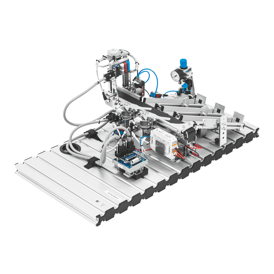
The workpieces must travel individually so as not to interfere with the switching operations of the deflectors. The sorting station sorts the workpieces according to material and color. The function of the station is to: Sort workpieces according to their characteristics © Festo Didactic 8046391... -
Page 37: The Detection Module
The fork light barrier detects all workpieces. The respective workpieces are detected by means of the logic operation of the output signals. The detection module can be mounted directly to a conveyor module. © Festo Didactic 8046391... -
Page 38: The Conveyor Module
Sensor (inductive proximity sensor) for deflector 1 extended signal Sensor (inductive proximity sensor) for deflector 2 extended signal Both deflectors are equipped with an ejector instead of a feed separator. The conveyor module should only run in one direction. © Festo Didactic 8046391... -
Page 39: The Chute Module
5 workpieces fit onto the chute. Three chute modules are used in the sorting station. Workpieces arriving on the conveyor module are stored on the chute module. A retro-reflective sensor monitors the fill-levels of the chutes. © Festo Didactic 8046391... -
Page 40: Function
5. Workpiece sorted out 6. Idle step Metallic workpiece detected, stored to the chute at the middle of the conveyor belt 7. Extend deflector 2 8. Retract stopper 9. Workpiece sorted out 10. Retract deflector 2 © Festo Didactic 8046391... - Page 41 Red workpiece detected, stored to the chute at the beginning of the conveyor belt 11. Extend deflector 1 12. Retract stopper 13. Workpiece sorted out 14. Retract deflector 1 15. Conveyor motor off 16. Advance stopper © Festo Didactic 8046391...
-
Page 42: Commissioning
A PLC board with 16 digital inputs and outputs A power supply unit: 24 V DC, 4.5 A Compressed air supply: 600 kPa (6 bar) A PC with installed PLC programming software Two I/O cables (SysLink) © Festo Didactic 8046391... -
Page 43: Mounting The Profile Plate And The Control Console
3. PLC board to power supply unit Insert the 4 mm safety plugs into the sockets on the power supply unit. 4. PC to PLC Connect your PC to the PLC via a programming cable. © Festo Didactic 8046391... -
Page 44: Power Supply
Current PLC programs for various controllers can be found on the Internet at the following website: www.festo-didactic.com > Services > MPS® The Modular Production System > Stations 10.6 Starting the sequence 1. Check power supply and compressed air supply. - Page 45 Do not use aggressive or abrasive cleaning agents. 12 Further information and updates Further information and updates for the technical documentation for the MPS stations are available on the following website: www.festo-didactic.com > Services > MPS® The Modular Production System © Festo Didactic 8046391...
- Page 46 Sorting Station © Festo Didactic 8046391...
- Page 47 Montaje de la placa perfilada y del panel de mando ______________________________________ 65 10.3 Conexiones mediante cables ________________________________________________________ 65 10.4 Fuente de alimentación ____________________________________________________________ 66 10.5 Cargar programas PLC _____________________________________________________________ 66 10.6 Inicio de la secuencia ______________________________________________________________ 66 © Festo Didactic 8046391...
- Page 48 Contenido Cuidados y mantenimiento _________________________________________________________ 67 Informaciones complementarias y actualizaciones______________________________________ 67 © Festo Didactic 8046391...
-
Page 49: Condiciones Generales Para El Uso De Los Equipos
Además, debe desconectarse en último lugar, después de desconectar la tensión. Si no se indica lo contrario en los datos técnicos, el aparato no contiene un fusible integrado. © Festo Didactic 8046391... -
Page 50: Pictogramas
Festo Didactic haya ocasionado dichos daños premeditadamente o con extrema negligencia. -
Page 51: Indicaciones De Seguridad
A pesar de ello, su utilización puede generar peligros que podrían afectar la integridad física o poner en peligro la vida de los usuarios o de terceros, así como también provocar daños en la máquina u otros daños materiales. © Festo Didactic 8046391... -
Page 52: Trabajar Con Seguridad
(por ejemplo, un destornillador). Efectúe el montaje de todos los componentes de tal manera que pueda acceder fácilmente a los interruptores y a las conexiones. Respete las indicaciones sobre el posicionamiento de los componentes. © Festo Didactic 8046391... - Page 53 Si no se indica lo contrario en los datos técnicos, el aparato no contiene un fusible integrado. Al desconectar los cables, tire únicamente de los conectores de seguridad, nunca de los cables. © Festo Didactic 8046391...
- Page 54 Utilizando silenciadores, o bien tapones para los oídos si no fuese posible evitar los ruidos. – Todas las conexiones de escape de aire deberán estar provistos de silenciadores. No retire esos silenciadores. © Festo Didactic 8046391...
-
Page 55: Datos Técnicos
Tubo flexible de material sintético de diámetro exterior de 6 mm Consumo de aire comprimido a 600 kPa (ciclo continuo) 3 l/min Dimensiones 350 mm x 700 mm x 230 mm Reservado el derecho de modificación © Festo Didactic 8046391... -
Page 56: Tabla De Ocupación De Contactos
Alimentación de 0 V en las salidas GND B 23+24 Blanco y azul Alimentación de 0 V en las entradas Nota En todas las variantes de PLC, los cables que puentean la parada de emergencia están conectados a bit 1.5. © Festo Didactic 8046391... -
Page 57: Transporte / Desembalaje / Dotación Del Suministro
La caja deberá moverse únicamente utilizando una carretilla elevadora apropiada. La caja deberá estar asegurada de tal manera que no pueda caerse. Cualquier daño ocurrido durante el transporte deberá notificarse de inmediato al transportista y a Festo Didactic. 6.2 Desembalaje Para sacar la estación de su caja de transporte, deberá... -
Page 58: Estructura
En la estación de clasificación, las piezas a manipular se clasifican según material y color. La función de la estación de clasificación consiste en clasificar piezas a manipular, diferenciándolas por sus características. © Festo Didactic 8046391... -
Page 59: El Módulo De Detección
La barrera óptica en horquilla detecta todas las piezas. Las piezas se diferencian aplicando un enlace lógico de las señales de salida. El módulo de detección pueden montarse directamente encima de la cinta transportadora. © Festo Didactic 8046391... -
Page 60: Módulo Cinta De Transporte
Sensor (sensor de proximidad inductivo) para el desvío 2, para la señal que indica que avanzó el desvío 2 Los dos desvíos están provistos de un elemento de expulsión, en vez de incluir una unidad separadora de piezas. El módulo de la cinta transportadora debería avanzar en un solo sentido. © Festo Didactic 8046391... -
Page 61: Módulo Plano Inclinado
Las piezas a manipular que provienen de la cinta transportadora se almacenan en el módulo de plano inclinado. El sensor de retroreflexión controla la cantidad de piezas acumuladas en el plano inclinado. © Festo Didactic 8046391... -
Page 62: Funcionamiento
Detectada una pieza a manipular metálica, colocación en el plano inclinado en la mitad de la cinta. 7. Avance del derivador 2 8. Retraer el tope 9. Pieza a manipular expulsada. 10. Retraer el derivador 2 © Festo Didactic 8046391... - Page 63 Detectada una pieza a manipular roja, colocación en el plano inclinado del inicio de la cinta. 11. Avanzar el derivador 1 12. Retraer el tope 13. Pieza a manipular expulsada. 14. Retraer el derivador 1 15. Motor de la cinta desconectado 16. Extender el tope. © Festo Didactic 8046391...
-
Page 64: Puesta En Funcionamiento
Una placa PLC con 16 entradas y salidas digitales Una unidad de alimentaciónde 24 V DC, 4,5 A Una alimentación de aire comprimido con 600 kPa (6 bar) Un PC con software de programación PLC instalado Dos cables E/S (SysLink) © Festo Didactic 8046391... -
Page 65: Montaje De La Placa Perfilada Y Del Panel De Mando
3. Placa PLC – Unidad de alimentación eléctrica Conecte los conectores de seguridad de 4 mm a los conectores de la unidad de alimentación. 4. PC – PLC Conecte el PC al PLC mediante un cable de programación. © Festo Didactic 8046391... -
Page 66: Fuente De Alimentación
En la dirección Internet que se indica a continuación encontrará programas PLC modernos, para diversos tipos de unidades de control. www.festo-didactic.com > Asistencia técnica> MPS® Sistemas mecatrónicos > Estaciones 10.6 Inicio de la secuencia 1. Compruebe la alimentación y el consumo de aire comprimido. - Page 67 12 Informaciones complementarias y actualizaciones En la dirección Internet que se indica a continuación se ofrecen informaciones complementarias y ® actualizaciones de la documentación técnica de las estaciones MPS www.festo-didactic.com > Servicio y Asistencia > MPS® Sistema de Producción © Festo Didactic 8046391...
- Page 68 Estación de clasificación © Festo Didactic 8046391...
- Page 69 Poste de travail ___________________________________________________________________ 86 10.2 Montage de la plaque profilée et du pupitre de commande ________________________________ 87 10.3 Câblage _________________________________________________________________________ 87 10.4 Alimentation électrique ____________________________________________________________ 88 10.5 Chargement des programmes API ____________________________________________________ 88 10.6 Démarrage du cycle _______________________________________________________________ 88 © Festo Didactic 8046391...
- Page 70 Table des matières Maintenance et entretien __________________________________________________________ 89 Informations complémentaires et mises à jour _________________________________________ 89 © Festo Didactic 8046391...
-
Page 71: Conditions Générales D'exploitation Des Appareils
La terre de protection doit toujours être raccordée en premier (avant la tension) et être débranchée en dernier (après coupure de la tension). Sauf indications contraires dans les caractéristiques techniques, l'appareil ne possède pas de fusible intégré. © Festo Didactic 8046391... -
Page 72: Pictogrammes
Le système de formation de Festo Didactic est exclusivement destiné à la formation initiale et continue dans le domaine de l’automatisation et de la technique. Il incombe à l’établissement de formation et/ou aux formateurs de faire respecter par les étudiants les consignes de sécurité... -
Page 73: Pour Votre Sécurité
Son utilisation peut néanmoins mettre en danger la vie et la santé de l’utilisateur ou de tiers ainsi qu’affecter l’intégrité de la machine ou d’autres biens. © Festo Didactic 8046391... -
Page 74: Travailler En Toute Sécurité
Utilisez un outil, par exemple un tournevis, pour actionner les capteurs de fin de course. Installez les composants de telle sorte qu'ils ne gênent pas l'actionnement d'interrupteurs ni de dispositifs de sectionnement de l'alimentation. Notez les indications concernant l'implantation des composants. © Festo Didactic 8046391... - Page 75 à la terre par un fil de protection. Sauf indications contraires dans les caractéristiques techniques, l'appareil ne possède pas de fusible intégré. Pour débrancher les câbles de liaison, tirez sur les connecteurs, pas sur les câbles. © Festo Didactic 8046391...
- Page 76 Le bruit produit par l'échappement d'air comprimé peut nuire à l'ouïe. Réduisez le bruit en utilisant des silencieux ou portez un casque anti-bruit si le bruit est inévitable. – Équipez tous les orifices d'échappement des jeux d'équipement de silencieux. Ne retirez pas ces silencieux. © Festo Didactic 8046391...
-
Page 77: Caractéristiques Techniques
Connecteur femelle IEEE-488 24 pôles (SysLink) Raccordement pneumatique Tuyau en plastique de 6 mm de diamètre extérieur Consommation d'air comprimé sous 600 kPa (cycle permanent) 3 l/min Dimensions 350 mm x 700 mm x 230 mm Sous réserve de modifications © Festo Didactic 8046391... -
Page 78: Brochage
0 V alimentation des sorties GND A lilas 0 V alimentation des sorties GND B 23+24 blanc/bleu 0 V alimentation des entrées Nota Sur toutes les variantes préférentielles d'API, des cavaliers sont enfichés entre ARRÊT D’URGENCE et le bit 1.5. © Festo Didactic 8046391... -
Page 79: Transport/Déballage/Fourniture
La caisse doit être exclusivement manutentionnée au moyen de transpalettes ou de chariots à fourche appropriés. Il convient de faire en sorte que la caisse ne puisse se renverser ni tomber. Tout dommage dû au transport doit être immédiatement signalé au transporteur et à Festo Didactic. 6.2 Déballage Au déballage de la station, retirez avec précaution le matériau de calage de la caisse. -
Page 80: Architecture
Sur la station de tri, les pièces sont triées en fonction de leur matière et de leur couleur. La mission de la station de tri est de : Tri des pièces en fonction de leur constitution © Festo Didactic 8046391... -
Page 81: Le Module D'identification
Le détecteur à réflexion détecte la pièce rouge et la pièce métallique La cellule photoélectrique à fourche détecte toutes les pièces. Une opération logique sur les signaux de sortie permet d'identifier chaque pièce. Le module d'identification se monte directement sur le module convoyeur. © Festo Didactic 8046391... -
Page 82: Le Module Convoyeur
(capteur de proximité inductif) sur le composant aiguillage 2 signalant aiguillage 2 sorti les deux composants aiguillage équipés non pas d'un séparateur mais d'un « éjecteur » Le module convoyeur doit fonctionner dans une seule direction. © Festo Didactic 8046391... -
Page 83: Le Module Goulotte
Si la butée mécanique est montée, la goulotte peut contenir 5 pièces. La station de tri utilise par trois fois le module goulotte. Le module goulotte stocke les pièces arrivant du module convoyeur. Une barrière photo-électrique surveille le niveau de remplissage des goulottes. © Festo Didactic 8046391... -
Page 84: Fonctionnement
5. Pièce évacuée 6. Pas à vide Pièce à usiner métallique détectée, dépôt sur la goulotte en milieu de bande 7. Sortir l'aiguillage 2 8. Rentrer le barrage 9. Pièce évacuée 10. Rentrer la dérivation 2 © Festo Didactic 8046391... - Page 85 Pièce rouge détectée, dépose sur la goulotte en début du convoyeur 11. Sortir l'aiguillage 1 12. Rentrer le barrage 13. Pièce évacuée 14. Rentrer la dérivation 1 15. Moteur du convoyeur à l’arrêt 16. Sortir le barrage. © Festo Didactic 8046391...
-
Page 86: Mise En Service
24 V CC, 4,5 A, une alimentation en air comprimé à 600 kPa (6 bar), un PC sur lequel est installé un logiciel de programmation d’API et deux câbles d’E/S (SysLink). © Festo Didactic 8046391... -
Page 87: Montage De La Plaque Profilée Et Du Pupitre De Commande
SysLink du pupitre de commande. 3. Carte API – Bloc d’alimentation Branchez les fiches de sécurité de 4 mm aux douilles du bloc d'alimentation. 4. PC – API Reliez votre PC à l'API par un câble de programmation. © Festo Didactic 8046391... -
Page 88: Alimentation Électrique
Vous trouverez les programmes API actuels pour différents automates sur Internet, à l'adresse suivante : www.festo-didactic.com > Service > Systèmes mécatroniques MPS® > Stations 10.6 Démarrage du cycle 1. Vérifiez l'alimentation en tension et en air comprimé. - Page 89 12 Informations complémentaires et mises à jour ® La documentation technique des stations MPS fait l’objet d’informations complémentaires et mises à jour que vous trouverez sur Internet à l’adresse : www.festo-didactic.com > Service > Systèmes mécatroniques MPS® © Festo Didactic 8046391...
- Page 90 Station de tri © Festo Didactic 8046391...
- Page 92 Festo Didactic SE Rechbergstraße 3 73770 Denkendorf Germany +49 711 3467-0 www.festo-didactic.com +49 711 34754-88500 did@festo.com...
Need help?
Do you have a question about the MPS 8046325 and is the answer not in the manual?
Questions and answers