
Related Manuals for Festo MPS


Summary of Contents for Festo MPS
- Page 1 Station Handhaben Handbuch Handling station Manual CD-ROM included 655633 de/en 07/18 R2.6...
- Page 2 Ausbildungsunternehmens und/oder sonstiger Dritter aus, die bei Gebrauch/Einsatz der Anlage außerhalb einer reinen Ausbildungssituation auftreten; es sei denn Festo Didactic hat solche Schäden vorsätzlich oder grob fahrlässig verursacht. This station has been developed and produced solely for vocational and further training purposes in the field of automation and communication.
-
Page 3: Table Of Contents
Endanschläge der Linearachse ____________________________________ 32 Sensoren justieren ______________________________________________ 34 6.4.1 Reflex-Lichttaster (Aufnahme, Werkstücknachweis) ___________________ 34 6.4.2 Reflex-Lichttaster (Greifer, Farberkennung) __________________________ 35 6.4.3 Näherungsschalter (PicAlfa, Linearachse) ___________________________ 37 6.4.4 Näherungsschalter (PicAlfa, Hebezylinder) __________________________ 38 Dosselrückschlagventile einstellen _________________________________ 39 © Festo Didactic 655633... - Page 4 Handhilfsbetätigung (HHB) _______________________________________ 41 Spannungsversorgung ___________________________________________ 41 6.10 SPS Programm laden ____________________________________________ 42 6.10.1 Siemens Steuerungen ___________________________________________ 42 6.10.2 Festo Steuerungen ______________________________________________ 45 6.10.3 Allen Bradley Steuerungen _______________________________________ 47 6.10.4 Mitsubishi/MELSEC Steuerungen __________________________________ 50 6.11 Ablauf starten __________________________________________________ 52 6.12 Kombination von Stationen _______________________________________ 53 6.12.1 Vernetzung ____________________________________________________ 53...
- Page 5 Diffuse sensor (Receptacle, detection of workpiece ) __________________ 90 6.4.2 Diffuse sensor (Gripper, colour distinction) __________________________ 91 6.4.3 Proximity sensor (PicAlfa, linear axis) _______________________________ 93 6.4.4 Proximity sensor (PicAlfa, lifting cylinder) ___________________________ 94 Adjusting one-way flow control valves ______________________________ 95 © Festo Didactic 655633...
- Page 6 Manual override ________________________________________________ 97 Voltage supply _________________________________________________ 97 6.10 Loading the PLC program _________________________________________ 98 6.10.1 Siemens controller ______________________________________________ 98 6.10.2 Festo controller ________________________________________________ 101 6.10.3 Allen Bradley controller _________________________________________ 103 6.10.4 Mitsubishi/MELSEC controller ____________________________________ 106 6.11 Starting the sequence __________________________________________ 108 6.12...
-
Page 7: Einleitung
Einleitung Das Lernsystem Automatisierung von Festo Didactic orientiert sich an unterschiedlichen Bildungsvoraussetzungen und beruflichen Anforderungen. Die Anlagen und Stationen des Modularen Produktions-Systems (MPS ) ermöglichen eine an der betrieblichen Realität ausgerichtete Aus- und Weiterbildung. Die Hardware setzt sich aus didaktisch aufbereiteten Industriekomponenten zusammen. -
Page 8: Lerninhalte
Systematische Fehlersuche an einer Fertigungsanlage – Themen für Projektarbeiten • Auswahl pneumatischer Komponenten Parallelgreifer – • Einsatz elektrischer Antriebe Linearachse mit Antrieb durch Gleichstrommotor – • Sicherheit bei pneumatischem Energieausfall Druckluftspeicher – • Optimieren der Zykluszeit © Festo Didactic 655633... -
Page 9: Wichtige Hinweise
Wichtige Hinweise Betrieb des MPS ist die Kenntnis der grundlegenden Sicherheitshinweise und der Sicherheitsvorschriften Dieses Handbuch enthält die wichtigsten Hinweise, um das MPS sicherheitsgerecht zu betreiben. Insbesondere die Sicherheitshinweise sind von allen Personen zu beachten, die am arbeiten. -
Page 10: Gefahren Im Umgang Mit Dem Modularen Produktions-System
Produktions-System der Maschine oder an anderen Sachwerten entstehen. Das MPS ist nur zu benutzen: • für die bestimmungsgemäße Verwendung und • in sicherheitstechnisch einwandfreiem Zustand. Störungen, die die Sicherheit beeinträchtigen können, sind umgehend zu beseitigen! © Festo Didactic 655633... -
Page 11: Gewährleistung Und Haftung
Ursachen zurückzuführen sind: • Nicht bestimmungsgemäße Verwendung des MPS • Unsachgemäßes Montieren, in Betrieb nehmen, Bedienen und Warten des MPS • Betreiben des MPS bei defekten Sicherheitseinrichtungen oder nicht ordnungsgemäß angebrachten oder nicht funktionsfähigen Sicherheits- und Schutzvorrichtungen •... -
Page 12: Sicherheitshinweise
• Überschreiten Sie nicht den maximalen Betriebsdruck der Station Handhaben von 400 kPa (4 bar). Mechanik • Montieren Sie alle Elemente fest auf die Platte. • Greifen Sie nur bei Stillstand in die Station. © Festo Didactic 655633... -
Page 13: Technische Daten
Technische Daten Parameter Wert Betriebsdruck 400 kPa (4 bar) Spannungsversorgung 24 V DC, 4,5 A Digitale Eingänge Digitale Ausgänge Kombinationen Mögliche direkte MPS Folgestationen Prüfen Hand- Puffern Pick& Fluidic- Trennen Lagern Roboter Montieren* Sortieren** arbeiten haben Place Muscle ... - Page 14 3. Technische Daten © Festo Didactic 655633...
-
Page 15: Transport/Auspacken/Lieferumfang
Die Transportbox darf ausschließlich mit geeigneten Hubwagen oder Gabelstaplern transportiert werden. Die Transportbox muss gegen Umfallen und Herunterfallen gesichert sein. Transportschäden sind unverzüglich dem Spediteur und Festo Didactic zu melden. Auspacken Beim Auspacken der Station das Füllmaterial der Transportbox vorsichtig entfernen. - Page 16 4. Transport/Auspacken/Lieferumfang © Festo Didactic 655633...
-
Page 17: Aufbau Und Funktion
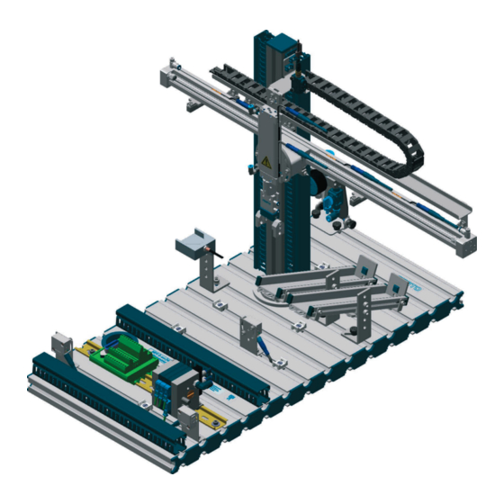
Die Station Handhaben Handhaben ist eine Teilfunktion des Materialflusses. Weitere Teilfunktionen sind Fördern und Lagern (Speichern). Nach VDI 2860 ist Handhaben das Schaffen, definierte Verändern oder vorübergehende Aufrechterhalten einer vorgegebenen räumlichen Anordnung von geometrisch bestimmten Körpern. © Festo Didactic 655633... - Page 18 • die Werkstücke auf der Rutsche 'metallisch/rot' oder der Rutsche 'schwarz' abzulegen oder • die Werkstücke an eine Folgestation weiterzugeben. Der Aufbau der Station Handhaben besteht aus: • Modul Aufnahme • Modul PicAlfa • Modul Rutsche • Profilplatte Station Handhaben mit Wagen, Bedienpult und SPS Board © Festo Didactic 655633...
-
Page 19: Funktion
Aussortierkriterien definiert werden. Durch geänderte Einstellung der mechanischen Endanschläge können Werkstücke auch an eine nachfolgende Station übergeben werden. Startvoraussetzung • Ein Werkstück in der Werkstückaufnahme Ablaufbeschreibung Ausgangsstellung • Linearachse in Position „Vorgängerstation“ • Hubzylinder eingefahren (Greifer oben) • Greifer geöffnet © Festo Didactic 655633... - Page 20 9. Die Linearachse fährt die Position „Rutsche 2“ an. 10. Der Hubzylinder fährt aus. 11. Der Greifer wird geöffnet, das Werkstück auf der Rutsche abgelegt. 12. Der Hubzylinder fährt ein. 13. Die Linearachse fährt in die Position „Vorgängerstation“. © Festo Didactic 655633...
-
Page 21: Modul Aufnahme
5. Aufbau und Funktion Modul Aufnahme In das Modul Aufnahme werden Werkstücke von Hand oder von einer Vorgängerstation eingelegt. Die Werkstücke werden in der Aufnahme von einem optischen Reflex-Lichttaster erkannt. © Festo Didactic 655633... -
Page 22: Modul Picalfa-Pneumatisch
Näherungsschalter erkennt die Werkstücke. Das Modul PicAlfa ist außerordentlich flexibel: Hublänge, Neigung der Achsen, Anordnung der Endlagensensoren und die Montageposition lassen sich einstellen. Dadurch kann das Modul an unterschiedlichste Handlingaufgaben ohne zusätzliche Elemente angepasst werden. © Festo Didactic 655633... -
Page 23: Modul Picalfa-Elektrisch
5. Aufbau und Funktion Modul PicAlfa-elektrisch Im Modul PicAlfa-elektrisch wird eine elektrische angetriebene Linearachse eingesetzt. Induktive Näherungsschalter fragen die Position des Schlittens über eine Schaltfahne ab. Hubzylinder und Greifer sind identisch wie bei dem Modul PicAlfa-pneumatisch. © Festo Didactic 655633... - Page 24 • der Motorcontroller zur Ansteuerung des 24 VDC Gleichstrommotors, • die Ventilinsel mit zwei 5/2-Wege-Magnetventilen, einem 5/2-Wege- Magnetimpulsventil und einem Multipolanschluss für die Ventilspulen Am beweglichen Teil des Schlittens befindet sich • der optische Näherungsschalter (Lichtleitergerät) zur Erfassung der Werkstücke im Greifer montiert. © Festo Didactic 655633...
-
Page 25: Modul Rutsche
Modul Rutsche Das Modul Rutsche dient zum Transportieren und Speichern von Werkstücken. Die Rutsche kann 5 Werkstücke aufnehmen. Der Neigungswinkel der Rutsche kann stufenlos eingestellt werden. In der Station Handhaben wird das Modul Rutsche zweimal verwendet. © Festo Didactic 655633... - Page 26 5. Aufbau und Funktion © Festo Didactic 655633...
-
Page 27: Inbetriebnahme
Zur Inbetriebnahme der MPS Station benötigen Sie: Arbeitsplatz • die montierte und justierte MPS Station • ein Bedienpult • ein SPS Board • ein Netzgerät 24 V DC, 4,5 A • eine Druckluftversorgung mit 400 kPa (4 bar), Saugleistung ca. 50 l/min •... -
Page 28: Mechanischer Aufbau
6. Inbetriebnahme 6.2.1 Montage von Profilplatte und Bedienpult Mechanischer Aufbau 2 (4x) 4 (4x) 5 (2x) Profilplatte Hammermutter M6-32 (4x) Wagen Zylinderschraube M6x10 (4x) Blechschraube 3,5x9 (2x) Bedienpult © Festo Didactic 655633... -
Page 29: Montage Der Station
6. Inbetriebnahme 6.2.2 Montage der Station Hinweise zur Montage der Station entnehmen Sie bitte der Montageanleitung der Station Handhaben im Verzeichnis Deutsch\4_Handhaben\Montageanleitungen der mitgelieferten CD-ROM. © Festo Didactic 655633... -
Page 30: Endanschläge Der Linearachse
Greifer sicher auf die Rutsche abgelegt werden. 7. Schieben Sie den mechanischen Endanschlag gegen den Schlitten der Linearachse. Fixieren Sie den mechanischen Endanschlag. 8. Schalten Sie die Druckluftversorgung aus. 9. Stellen Sie die pneumatischen Anschlüsse des Hebezylinders und der Linearachse her. © Festo Didactic 655633... - Page 31 Handhilfsbetätigungen der Magnetventile. Dokumente • Datenblätter Näherungsschalter SME-8 (150857) im Verzeichnis Deutsch\4_Handhaben\Datenblaetter der mitgelieferten CD-ROM. • Bedienungsanleitungen Näherungsschalter SME-8 (646518) im Verzeichnis Deutsch\4_Handhaben\Bedienungsanleitungen der mitgelieferten CD-ROM. • Montageanleitungen Station Handhaben im Verzeichnis Deutsch\4_Handhaben\Montageanleitungen der mitgelieferten CD-ROM. © Festo Didactic 655633...
-
Page 32: Sensoren Justieren
Lichtleitergerät SOEG_L (165327) und Lichtleiter Reflex SOEZ-RT (165358) im Verzeichnis Deutsch\4_Handhaben\Datenblaetter der mitgelieferten CD-ROM. • Bedienungsanleitungen Lichtleitergerät (369669) und Lichtleiter Reflex (369682) im Verzeichnis Deutsch\4_Handhaben\Bedienungsanleitungen der mitgelieferten CD-ROM. • Montageanleitungen Station Handhaben im Verzeichnis Deutsch\4_Handhaben\Montageanleitungen der mitgelieferten CD-ROM. © Festo Didactic 655633... -
Page 33: Reflex-Lichttaster (Greifer, Farberkennung)
Schaltzustandsanzeige (LED) ausschaltet. Hinweis Maximal 12 Umdrehungen der Einstellschraube sind zulässig. 7. Kontrollieren Sie die Einstellung durch Greifen schwarzer, roter und silberner Werkstücke. Hinweis Rote und silberne Werkstücke müssen sicher erkannt werden. Schwarze Werkstücke dürfen nicht erkannt werden. © Festo Didactic 655633... - Page 34 Lichtleitergerät SOEG_L (165327) und Lichtleiter Reflex SOEZ-RT (165358) im Verzeichnis Deutsch\4_Handhaben\Datenblaetter der mitgelieferten CD-ROM. • Bedienungsanleitungen Lichtleitergerät (369669) und Lichtleiter Reflex (369682) im Verzeichnis Deutsch\4_Handhaben\Bedienungsanleitungen der mitgelieferten CD-ROM. • Montageanleitungen Station Handhaben im Verzeichnis Deutsch\4_Handhaben\Montageanleitungen der mitgelieferten CD-ROM. © Festo Didactic 655633...
-
Page 35: Näherungsschalter (Picalfa, Linearachse)
(Abholposition/Rutsche 1/Rutsche 2). Dokumente • Datenblätter Näherungsschalter SME-8 (150857) im Verzeichnis Deutsch\4_Handhaben\Datenblaetter der mitgelieferten CD-ROM. • Bedienungsanleitungen Näherungsschalter SME-8 (646518) im Verzeichnis Deutsch\4_Handhaben\Bedienungsanleitungen der mitgelieferten CD-ROM. • Montageanleitungen Station Handhaben im Verzeichnis Deutsch\4_Handhaben\Montageanleitungen der mitgelieferten CD-ROM. © Festo Didactic 655633... -
Page 36: Näherungsschalter (Picalfa, Hebezylinder)
Probeläufe des Hebezylinders (ein-/ausfahren). Dokumente • Datenblätter Näherungsschalter SME-8 (150857) im Verzeichnis Deutsch\4_Handhaben\Datenblaetter der mitgelieferten CD-ROM. • Bedienungsanleitungen Näherungsschalter SME-8 (646518) im Verzeichnis Deutsch\4_Handhaben\Bedienungsanleitungen der mitgelieferten CD-ROM. • Montageanleitungen Station Handhaben im Verzeichnis Deutsch\4_Handhaben\Montageanleitungen der mitgelieferten CD-ROM. © Festo Didactic 655633... -
Page 37: Dosselrückschlagventile Einstellen
Überprüfen Sie vor dem Start der Station: • die elektrischen Anschlüsse • den korrekten Sitz und den Zustand der Druckluftanschlüsse • die mechanischen Komponenten auf sichtbare Defekte (Risse, lose Verbindungen usw.) Beseitigen Sie entdeckte Schäden vor dem Start der Station! © Festo Didactic 655633... -
Page 38: Kabelverbindungen
Stecken Sie den Stecker XMG1 des SPS Boards in die Buchse XMG1 des Bedienpults. 3. SPS Board – Netzgerät Stecken Sie die 4 mm Sicherheitsstecker in die Buchsen des Netzgerätes. 4. PC – SPS Verbinden Sie Ihren PC durch ein Programmierkabel mit der SPS. © Festo Didactic 655633... -
Page 39: Pneumatischer Anschluss
CPV Ventilinsel (165100) im Verzeichnis Deutsch\4_Handhaben\Bedienungsanleitungen der mitgelieferten CD-ROM. • Die Stationen werden über ein Netzgerät mit 24 V Gleichspannung (max. 5 A) Spannungsversorgung versorgt. • Die Spannungsversorgung der kompletten Station erfolgt über das SPS Board. © Festo Didactic 655633... -
Page 40: Sps Programm Laden
– Sie können den Betriebsartenschalter loslassen. Er geht dabei selbsttätig in – die STOP Stellung. Die SPS ist urgelöscht und zum Laden der Programme bereit. – 6. Betriebsartenschalter in Position STOP 7. Starten Sie die Programmiersoftware © Festo Didactic 655633... - Page 41 9. Wählen Sie die entsprechende Hardwarekonfiguration und laden Sie diese in Ihre SPS: – SPS 313C – SPS 313C 2DP – SPS 314 – SPS 315 2DP 10. Wählen Sie das Projekt 4HA_AS oder 4HA_KFA (AS = Ablaufsprache, KFA = KOP/FUP/AWL) © Festo Didactic 655633...
- Page 42 6. Inbetriebnahme 11. Laden Sie das Projekt in die Steuerung Zielsystem Laden Folgen Sie den Anweisungen auf dem Bildschirm 12. Betriebsartenschalter in Position RUN © Festo Didactic 655633...
-
Page 43: Festo Steuerungen
6. Inbetriebnahme 6.10.2 Festo Steuerungen • Steuerungen: Festo FEC FC640, IPC CPU HC02, IPC CPU HC20 • Programmiersoftware: Festo FST Version 4.02 1. PC und Steuerung mit dem Programmierkabel TTL-RS232 verbinden 2. Netzgerät einschalten 3. Druckluftversorgung einschalten 4. NOT-AUS Taster entriegeln (falls vorhanden) 5. - Page 44 6. Inbetriebnahme 8. Kompilieren Sie das Projekt Projekt Alles übersetzen 9. Laden Sie das Projekt in die Steuerung Online Projekt laden Folgen Sie den Anweisungen auf dem Bildschirm © Festo Didactic 655633...
-
Page 45: Allen Bradley Steuerungen
Communications Configure Drivers… in der Liste “Available Driver Types“ die Einstellung “RS-232 DF1 devices“ wählen und auf Add New…klicken Meldung (“Choose a name…“, Vorgabe: AB_DF1-1) mit OK bestätigen Auto configure OK Close © Festo Didactic 655633... - Page 46 Processor Memory und bestätigen Sie mit OK. Wenn die COMM 0.-LED erlischt, ist der Speicher der SPS gelöscht und zum – Laden der Programme bereit. 6. Öffnen Sie die Projektdatei 04_HA_K im Verzeichnis Quellen\ SPS Programme\Release C\ML 1500 der mitgelieferten CD-ROM. © Festo Didactic 655633...
- Page 47 Comms. System Comms. Steuerung auswählen, auf Download klicken. Bestätigen Sie die nachfolgenden Meldungen ("Revision note","…sure to proceed with Download?", "…want to go online?") mit Ja bzw. OK 8. Betriebsartenschalter in Position REM bzw. RUN © Festo Didactic 655633...
-
Page 48: Mitsubishi/Melsec Steuerungen
6. Dearchivieren Sie die Projektdatei 04_HA_AS.pcd im Verzeichnis Quellen\ SPS Programme\Release C\FX1N der mitgelieferten CD-ROM. Extras Project Restore … Projektdatei auswählen (CD ROM: Quellen\SPS Programme\Release C\FX1N) 04_HA_AS.pcd Öffnen Zielverzeichnis auswählen OK nachfolgende Meldung (“After saving,…”)mit OK bestätigen © Festo Didactic 655633... - Page 49 7. Kompilieren Sie das Projekt Project Rebuild all 8. Laden Sie das Projekt in die Steuerung Project Transfer Download to PLC… nachfolgende Meldungen ("Transfer to PLC", ….),mit OK bestätigen Betriebsartenschalter in Position RUN © Festo Didactic 655633...
-
Page 50: Ablauf Starten
• Der Ablauf kann durch Drücken des NOT-AUS Tasters oder durch Drücken des STOP Tasters jederzeit unterbrochen werden. • Mit dem Schlüsselschalter AUTO/MAN können Sie zwischen Dauerzyklus (AUTO) und Einzelzyklus (MAN) wählen. • Bei einer Kombination mehrerer Stationen gilt: Richten der einzelnen Stationen erfolgt entgegen dem Materialfluss. © Festo Didactic 655633... -
Page 51: Kombination Von Stationen
6.12 6.12.1 Vernetzung Kombination von Stationen In der Standardversion werden MPS Stationen mit optischen Sensoren gekoppelt. Diese Art der Kopplung wird mit StationLink bezeichnet. Als StationLink Sensoren werden Einweg-Lichtschranken Sender und Empfänger verwendet. Der StationLink Sender ist auf der Materialeingangsseite der Station montiert, der StationLink Empfänger auf der Materialausgangsseite. - Page 52 6. Inbetriebnahme © Festo Didactic 655633...
-
Page 53: Wartung
• die Linsen der optischen Sensoren, der Faseroptiken sowie Reflektoren • die aktive Fläche des Näherungsschalters • die gesamte Station mit einem weichen, fuselfreien Tuch oder Pinsel gereinigt werden. Es dürfen keine aggressiven oder scheuernde Reinigungsmittel verwendet werden. © Festo Didactic 655633... - Page 54 7. Wartung © Festo Didactic 655633...
-
Page 55: Inhalt Der Cd-Rom
369 662 Lichtschranke, Sender 369 679 Magnetischer Näherungsschalter SME-8 646 518 Parallelgreifer 377 641 Pneumatische Zylinder 391 172 Pneumatischer Linearantrieb DGC 696454 Ventilinsel CPV 165 100 Ventilinsel CPV-SC, elektrisch 702594 Ventilinsel CPV-SC, pneumatisch 530925 Zahnriemenachse EGC 731348 © Festo Didactic 655633... -
Page 56: Datenblätter
004 645 Steckdose mit Anschlusskabel SIM-M8-3GD 159 420 Steckdose mit Anschlusskabel SIM-M8-4GD 158 960 Steckverschraubung 153 333 Steckverschraubung 186 117 Stoßdämpfer 158 981 Ventilbausatz 5/3-Wege Magnetventil, Mittelstellung gesperrt 176 055 Ventilinsel CPV-SC 525675 Zahnriemenachse EGC 556812 © Festo Didactic 655633... -
Page 57: Aktualisierungen
Aktualisierungen Aktuelle Informationen und Ergänzungen zur Technischen Dokumentation der MPS Stationen finden Sie im Internet unter der Adresse: http://www.festo-didactic.de/Services > MPS © Festo Didactic 655633... - Page 58 Aktualisierungen © Festo Didactic 655633...
-
Page 59: Contents
Diffuse sensor (Receptacle, detection of workpiece ) __________________ 90 6.4.2 Diffuse sensor (Gripper, colour distinction) __________________________ 91 6.4.3 Proximity sensor (PicAlfa, linear axis) _______________________________ 93 6.4.4 Proximity sensor (PicAlfa, lifting cylinder) ___________________________ 94 Adjusting one-way flow control valves ______________________________ 95 © Festo Didactic 655633... - Page 60 Manual override ________________________________________________ 97 Voltage supply _________________________________________________ 97 6.10 Loading the PLC program _________________________________________ 98 6.10.1 Siemens controller ______________________________________________ 98 6.10.2 Festo controller ________________________________________________ 101 6.10.3 Allen Bradley controller _________________________________________ 103 6.10.4 Mitsubishi/MELSEC controller ____________________________________ 106 6.11 Starting the sequence __________________________________________ 108 6.12...
-
Page 61: Introduction
Introduction The Festo Didactic Learning System for Automation is designed to meet a number of different training and vocational requirements. The systems and stations of the Modular Production System (MPS ) facilitate industry-orientated vocational and further training and the hardware consists of didactically suitable industrial components. -
Page 62: Training Contents
Topics for project work • Selecting pneumatic components Parallel grippers – • Application of electric drives Linear axis with electric drive – • Safety during pneumatic power failure Compressed air reservoir – • Optimising cycle time © Festo Didactic 655633... -
Page 63: Important Notes
Important notes observe the fundamental safety recommendations and regulations. This manual contain important notes concerning the safe operation of the . MPS The safety recommendations in particular must be observed by anyone working on the MPS Furthermore, the rules and regulations for the prevention of accidents applicable to the place of use must be observed. -
Page 64: Risks Involved In Dealing With The Modular Production System
The MPS is to be used only: • for its intended purpose and • in an absolutely safe conditions. Faults impairing safety must be rectified immediately! © Festo Didactic 655633... -
Page 65: Warranty And Liability
• Incorrectly carried out repairs • Catastrophies as a result of foreign bodies and vis major. Festo Didactic herewith rules out any liability for damage or injury to trainees, the training company and/or other third parties which may occur during the use/operation of the system other than purely in a training situation, unless such damage has been caused intentionally or due to gross negligence by Festo Didactic. - Page 66 1. Introduction © Festo Didactic 655633...
-
Page 67: Notes On Safety
• Do not exceed the maximum operating pressure of the Handling station of 4 bar (400 kPa). Mechanics • Securely mount all components on the plate. • No manual intervention unless the machine is at rest. © Festo Didactic 655633... - Page 68 2. Notes on safety © Festo Didactic 655633...
-
Page 69: Technical Data
Technical data Parameter Value Operating pressure 4 bar (400 kPa) Voltage supply 24 V DC, 4.5 A Digital inputs Digital outputs Combinations Possible direct MPS downstream stations Testing Proces- Hand- Buffer Pick& Fluidic- Separat- Storing Robot Assembly* Sorting** sing... - Page 70 3. Technical data © Festo Didactic 655633...
-
Page 71: Transport/Unpacking/Scope Of Delivery
The container must be transported on a suitable fork lift truck at all times and must be secured against tipping or falling off. The carrier and Festo Didactic are to be notified immediately of any damage caused during transport. Unpacking Carefully remove the padding material in the container box when unpacking the station. - Page 72 4. Transport/Unpacking/Scope of delivery © Festo Didactic 655633...
-
Page 73: Design And Function
The Handling station Handling is a subfunction of material flow. Additional subfunctions are conveying and storing. According to VDI 2860, handling is the creation, defined changing or temporary maintaining of a specified spatial arrangement of geometrically determined bodies. © Festo Didactic 655633... - Page 74 • to pass on the workpieces to a subsequent station. The Handling station consists of the following: • Receptacle module • PicAlfa module • Slide module • Profile plate Handling station with trolley, control console and PLC board © Festo Didactic 655633...
-
Page 75: Function
By changing the setting of the mechanical end stops, it is also possible to transfer workpieces to a subsequent station. Starting prerequisites Sequence description • Workpiece in the receptacle Initial position • Linear axis in position “upstream station” • Lifting cylinder retracted (gripper is raised) • Gripper is open © Festo Didactic 655633... - Page 76 9. The linear axis approaches the position “slide 2”. 10. The lifting cylinder advances. 11. The gripper is opened and the workpiece deposited on the slide. 12. The lifting cylinder retracts. 13. The linear axis moves into the “upstream station” position. © Festo Didactic 655633...
-
Page 77: Receptacle Module
5. Design and function Receptacle module The workpieces are inserted manually into the Receptacle module. The workpieces are detected in the receptacle by an optical diffuse sensor. © Festo Didactic 655633... -
Page 78: Picalfa-Pneumatic Module
The PicAlfa module is exceptionally flexible: Stroke length, inclination of the axes, configuration of the end position sensors and the mounting position are adjustable. The module can therefore be adapted to a wide range of different handling tasks without the need for any additional components. © Festo Didactic 655633... -
Page 79: Picalfa-Electrical Module
5. Design and function PicAlfa-electrical module The PicAlfa-electrical module uses an electrical driven linear axis. The position of the slide is sensed electrically via inductive sensors. Lifting cylinder and gripper are the same as in the PicAlfa-pneumatic module. © Festo Didactic 655633... - Page 80 • a valve terminal equipped with two 5/2-way solenoid valves, one 5/2-way double solenoid valve and a multi-pin connector for the solenoid coils. On the moving part of the slide is • an optical proximity sensor (fibre-optic unit) sensing the workpieces picked-up by the gripper. © Festo Didactic 655633...
-
Page 81: Slide Module
Slide module The Slide module is used to transport and store workpieces. The slide can accommodate 5 workpieces. The angle of inclination of the slide is infinitely adjustable. Two slide modules are utilised in the Handling station. © Festo Didactic 655633... - Page 82 5. Design and function © Festo Didactic 655633...
-
Page 83: Commissioning
/ wiring and supply of operating voltage. All components, tubing and wiring is clearly marked so that all connections can be easily re-established. The following is required to commission the MPS station: Workstation • The assembled and adjusted MPS station •... -
Page 84: Mechanical Set Up
6. Commissioning 6.2.1 Assembling profile plate and control console Mechanical set up 2 (4x) 4 (4x) 5 (2x) Profile plate T-head nut M6 x-32 (4x) Trolley Socket head screw M6x10 (4x) Screw 3.5x9 (2x) Control console © Festo Didactic 655633... -
Page 85: Assembling The Station
6. Commissioning 6.2.2 Assembling the station Instructions on assembling the station please find in the assembly instructions of the Handling station in the directory English\4_Handling\Assembly instructions on the CD-ROM supplied. © Festo Didactic 655633... -
Page 86: End Stops Of The Linear Axis
7. Shift the mechanical end stop of the linear axis against the slide of the linear axis. Fix the end stop. 8. Switch off the compressed air supply. 9. Tube up the lifting cylinder and the linear axis. © Festo Didactic 655633... - Page 87 Proximity sensor SME-8 (150857) in the directory English\4_Handling\Data sheets on the CD-ROM supplied. • Operating instructions Proximity sensor SME-8 (646518) in the directory English\4_Handling\Operating instructions on the CD-ROM supplied. • Assembly instructions Handling station in the directory English\4_Handling\Assembly instructions on the CD-ROM supplied. © Festo Didactic 655633...
-
Page 88: Adjust Sensors
• Operating instructions Fibre optic unit (369669) and fibre optic cable diffuse (369682) in the directory English\4_Handling\Operating instructions on the CD-ROM supplied. • Assembly instructions Handling station in the directory English\4_Handling\Assembly instructions on the CD-ROM supplied. © Festo Didactic 655633... -
Page 89: Diffuse Sensor (Gripper, Colour Distinction)
Note Maximal 12 revolutions of the adjusting screw are permissible. 7. Check the setting of the fibre optic unit. Note Red and metallic workpieces should be detected securely, black workpieces not. © Festo Didactic 655633... - Page 90 • Operating instructions Fibre optic unit (369669) and fibre optic cable diffuse (369682) in the directory English\4_Handling\Operating instructions on the CD-ROM supplied. • Assembly instructions Handling station in the directory English\4_Handling\Assembly instructions on the CD-ROM supplied. © Festo Didactic 655633...
-
Page 91: Proximity Sensor (Picalfa, Linear Axis)
Proximity sensor SME-8 (150857) in the directory English\4_Handling\Data sheets on the CD-ROM supplied. • Operating instructions Proximity sensor (646518) in the directory English\4_Handling\Operating instructions on the CD-ROM supplied. • Assembly instructions Handling station in the directory English\4_Handling\Assembly instructions on the CD-ROM supplied. © Festo Didactic 655633... -
Page 92: Proximity Sensor (Picalfa, Lifting Cylinder)
Proximity sensor SME-8 (150857) in the directory English\4_Handling\Data sheets on the CD-ROM supplied. • Operating instructions Proximity sensor (646518) in the directory English\4_Handling\Operating instructions on the CD-ROM supplied. • Assembly instructions Handling station in the directory English\4_Handling\Assembly instructions on the CD-ROM supplied. © Festo Didactic 655633... -
Page 93: Adjusting One-Way Flow Control Valves
• The electrical connections • The correct installation and condition of the compressed air connections • The mechanical components for visual defects (tears, loose connections etc.) Eliminate any damage detected prior to starting up the station! © Festo Didactic 655633... -
Page 94: Cable Connections
3. PLC board – power supply unit Plug the 4 mm safety plugs into the sockets of the power supply unit. 4. PC – PLC Connect your PC to the PLC by means of a programming cable. © Festo Didactic 655633... -
Page 95: Pneumatic Connection
CD-ROM supplied. • The stations are supplied with 24 V DC voltage (max. 5 A) via a power supply Voltage supply unit. • The voltage supply of the complete station is effected via the PLC board. © Festo Didactic 655633... -
Page 96: Loading The Plc Program
You can let go of the mode selector switch. – When the STOP LED comes on permanently the memory reset is completed. – The PLC is ready for program download. – 6. mode selector switch in STOP position 7. Start the PLC programming software © Festo Didactic 655633... - Page 97 9. Select the hardware configuration and download it to the controller: – PLC 313C – PLC 313C 2DP – PLC 314 – PLC 315 2DP 10. Select the project 4HA_AS or 4HA_KFA (AS = sequential function chart, KFA = Ladder diagram/Function block diagram/Instruction list) © Festo Didactic 655633...
- Page 98 6. Commissioning 11. Download the project to the controller PLC Download Follow the instructions on the screen 12. Turn the mode selector switch of the CPU to RUN position © Festo Didactic 655633...
-
Page 99: Festo Controller
6. Commissioning 6.10.2 Festo controller • Controller: Festo FEC FC640, IPC CPU HC02, IPC CPU HC20 • Programming software: Festo FST Version 4.02 1. Connect PC and PLC using the TTL-RS232 programming cable 2. Switch on power supply unit 3. Switch on the compressed air supply 4. - Page 100 6. Commissioning 8. Compile the project Project Build Project 9. Download the project to the controller Online Download Projekt Follow the instructions on the screen © Festo Didactic 655633...
-
Page 101: Allen Bradley Controller
Communications Configure Drivers… select the setting “RS-232 DF1 devices“ from the list “Available Driver Types“ and click Add New… confirm note (“Choose a name…“, default: AB_DF1-1) with OK Auto configure OK Close © Festo Didactic 655633... - Page 102 When the COMM 0.- LED stops blinking the memory reset is completed. – The PLC is ready for program download. – 6. Open the file 04_HA_K from the directory Sources\PLC Programs\Release C\ ML 1500 of the CD-ROM supplied © Festo Didactic 655633...
- Page 103 Comms. System Comms. select controller, click Download Confirm the following notes (“Revision note","…sure to proceed with Download?", "…want to go online?") with Yes or OK 8. Turn the mode selector switch of the CPU to RUN position © Festo Didactic 655633...
-
Page 104: Mitsubishi/Melsec Controller
Release C\FX1N of the CD-ROM supplied Extras Project Restore … select a project file (CD ROM: Sources\PLC Programs\Release C\FX1N) 04_HA_AS.pcd Open Select destination directory OK Confirm the following note (“After saving,…”) with OK © Festo Didactic 655633... - Page 105 8. Download the project to the controller Project Transfer Download to PLC… Confirm the following notes ("Transfer to PLC", ….) with OK 9. Turn the mode selector switch of the CPU to RUN position © Festo Didactic 655633...
-
Page 106: Starting The Sequence
• The key-operated switch AUTO/MAN enables you to select between continuous cycle (AUTO) and individual cycle (MAN). • In the case of a combination of stations the following applies: The individual stations are reset against the material flow. © Festo Didactic 655633... -
Page 107: Combination Of Stations
6.12.1 Networking Combination of stations In the standard version, the MPS stations are linked using optical sensors. This type of linking is known as StationLink, which uses through-beam sensor transmitters and receivers as sensors. The StationLink transmitter is mounted on the incoming material side and the StationLink receiver on the outgoing material side. - Page 108 6. Commissioning © Festo Didactic 655633...
-
Page 109: Maintenance
• The lenses of the optical sensors, the fibre-optics and reflectors • The active surface of the proximity sensor • The entire station Do not use aggressive or abrasive cleaning agents. © Festo Didactic 655633... - Page 110 7. Maintenance © Festo Didactic 655633...
-
Page 111: Content Of The Cd-Rom
391 172 Pneumatic linear drive DGC 696454 Through-beam sensor, receiver 369 662 Through-beam sensor, transmitter 369 679 Toothed belt axis EGC 731348 Valve terminal CPV 165 200 Valve terminal CPV-SC, electrical 702594 Valve terminal CPV-SC, pneumatic 530926 © Festo Didactic 655633... -
Page 112: Data Sheets
Start-up valve with filter control valve 152 894 Through-beam sensor, receiver 165 323 Through-beam sensor, transmitter 165 353 Toothed belt drive EGC 556812 Valve kit 5/3-way solenoid valve, mid-position closed 176 055 Valve terminal CPV-SC 525675 © Festo Didactic 655633... -
Page 113: Updates
Updates Up-to-date information and additional documents for the Technical documentation of the MPS stations please find at the address: http://www.festo-didactic.de/Services > MPS © Festo Didactic 655633... - Page 114 Updates © Festo Didactic 655633...
- Page 116 Festo Didactic SE Rechbergstraße 3 73770 Denkendorf Germany +49 711 3467-0 www.festo-didactic.com +49 711 34754-88500 did@festo.com...
Need help?
Do you have a question about the MPS and is the answer not in the manual?
Questions and answers