Table of Contents
Advertisement
Quick Links
Advertisement
Table of Contents

Related Manuals for CYP CSC-109TX


Summary of Contents for CYP CSC-109TX
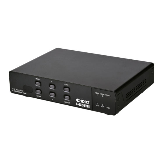
- Page 1 CSC-109TX HDMI/USB-C/VGA to HDMI/HDBaseT Scaler Operation Manual Operation Manual...
- Page 3 DISCLAIMERS The information in this manual has been carefully checked and is believed to be accurate. Cypress Technology assumes no responsibility for any infringements of patents or other rights of third parties which may result from its use. Cypress Technology assumes no responsibility for any inaccuracies that may be contained in this document.
- Page 4 SAFETY PRECAUTIONS Please read all instructions before attempting to unpack, install or operate this equipment and before connecting the power supply. Please keep the following in mind as you unpack and install this equipment: • Always follow basic safety precautions to reduce the risk of fire, electrical shock and injury to persons.
-
Page 5: Table Of Contents
CONTENTS 1. Introduction ............1 2. Applications ............. 1 3. Package Contents ........... 2 4. System Requirements ........2 5. Features............3 6. Operation Controls and Functions ....4 6.1 Front Panel ..........4 6.2 Rear Panel........... 5 6.3 Remote Control ........... 7 6.4 IR Cable Pinouts.......... -
Page 6: Introduction
1. INTRODUCTION This 5 by 2 multi-format scaling switcher provides HDMI, USB-C, HDBaseT, and VGA inputs which can be freely selected for output at a scaled resolution of the user’s choosing over the mirrored HDMI and HDBaseT outputs. The HDMI and USB-C ports support resolutions up to 4K@60 (4:4:4, 8-bit) while the HDBaseT output supports automatic color subsampling of 4K50/60(4:4:4) sources to 4K50/60(4:2:0). -
Page 7: Package Contents
3. PACKAGE CONTENTS • 1× HDMI/USB-C/VGA to HDMI/HDBaseT Scaler • 1× 24V/5A DC Power Adapter • 1× Remote Control (CR-192) • 1× IR Blaster Cable • 1× IR Extender Cable • 1× 3.5mm to 9-pin D-sub Male Cable • 1× 6-pin Terminal Block •... -
Page 8: Features
5. FEATURES • HDMI 2.0 and DVI 1.0 compliant • HDCP 1.x and 2.2 compliant • 5 video inputs (2×HDMI, 1×USB-C, 2×VGA) • 2 mirrored video outputs (1×HDMI, 1×HDBaseT) • Supports switching and scaling of all AV inputs for display over the mirrored HDMI and HDBaseT outputs •... -
Page 9: Operation Controls And Functions
6. OPERATION CONTROLS AND FUNCTIONS 6.1 Front Panel MENU LOCK HDMI HDMI USB-C LOCK UHD + Multi-Format ENTER SELECT to HDMI/HDBaseT Scaler POWER LED: This LED will illuminate to indicate the unit is on and receiving power. IR Window: Accepts IR signals from the included IR remote for control of this unit only. -
Page 10: Rear Panel
6.2 Rear Panel 9 10 11 AUDIO IN PHANTOM C 1 2 3 4 5 SERVICE LINE OUT MIC IN LINE IN VGA 1 VGA 2 IR OUT IR IN RS232 INPUT CONTROL RS-232 BYPASS USB-C IN USB-C IN HDMI 1 IN HDMI 2 IN VGA 1 IN VGA 2 IN... - Page 11 LINE IN Port: Connect to the stereo analog output of a device such as a CD player or PC. VGA 1~2 Ports: Connect to the stereo analog output of the device connected to the associated VGA input port. IR OUT Port: Connect to an IR Blaster to transmit IR signals from the other end of the HDBaseT connection to devices within direct line-of- sight of the IR Blaster.
-
Page 12: Remote Control
6.3 Remote Control HDMI 1~2, USB-C & VGA 1~2: HDMI1 HDMI2 USB-C Press any of these buttons to switch VGA1 VGA2 immediately to the corresponding input. MENU: Access the OSD menu. EXIT: Exit the OSD menu. EXIT MENU ▲/▼: Navigate up/down within the OSD menu items. -
Page 13: Ir Cable Pinouts
6.4 IR Cable Pinouts IR Blaster IR Extender Cable Cable Power Infrared Infrared Power Not Used Ground 6.5 RS-232 Pinout and Defaults Serial Port Default Settings Baud Rate 19200 Data Bits Parity Bits None Stop Bits Flow Control None RS-232 (Control) RS-232 (Bypass) 3.5mm to DE-9 Adapter Cable... -
Page 14: Osd Menu
6.6 OSD Menu All functions of this unit can be controlled by using the OSD (On Screen Display) which is activated by pressing the MENU button on the front of the unit. Use the + (PLUS), − (MINUS), and ENTER buttons to navigate the OSD menu. - Page 15 VIDEO 2ND LEVEL 3RD LEVEL 4TH LEVEL Output Routing HDMI 1 HDMI 2 USB-C VGA 1 VGA 2 Output Resolution NATIVE HDMI Native HDBT 640×480 60 800×600 60 1024×768 60 1280×768 60 1280×800 60 1280×1024 60 1360×768 60 1400×1050 60 1440×900 60 1600×1200 60 1680×1050 60...
- Page 16 VIDEO 2ND LEVEL 3RD LEVEL 4TH LEVEL 720×576p 50 1280×720p 50 1920×1080p 50 1920×1080p 24 1920×1080p 25 1920×1080p 30 2560×1080p 50 2560×1080p 60 3840×2160p 24 3840×2160p 25 3840×2160p 30 3840×2160p 50 3840×2160p 60 4096×2160p 24 4096×2160p 25 4096×2160p 30 4096×2160p 50 4096×2160p 60 Aspect FULL...
- Page 17 VIDEO 2ND LEVEL 3RD LEVEL 4TH LEVEL No Signal Color BLACK White Blue Green Blank Freeze Auto Setting Auto Sync Off 3 min 5 min 10 min Auto Video Routing AUTO SWTICH HDCP Setting HDMI 1 HDCP Support Off Refer to Source REFER TO DISPLAY HDMI 2 HDCP Support Off...
- Page 18 VIDEO 2ND LEVEL 3RD LEVEL 4TH LEVEL PC Setting PC Auto Setup Execute PC H Position 0~250 PC V Position 0~250 PC Phase 0~250 PC Clock 0~255 PC Reset 1) Output Routing: Select the video input to route to both outputs. 2) Output Resolution: Select the output resolution to use.
- Page 19 8) HDCP Setting: Provides control over the HDCP behavior of each input. 9) PC SETTING: This menu is only available when a VGA source is active. „ PC Auto: Provides a way to manually activate the auto detection of the VGA source’s signal parameters. Press “Enter” to activate. Note: For best results, a VGA source with a bright image that extends to all 4 edges of the screen should be displayed when this is activated.
- Page 20 PICTURE 2ND LEVEL 3RD LEVEL Color Gain R 0~1023 (512) Color Gain G 0~1023 (512) Color Gain B 0~1023 (512) Color Offset R 0~1023 (512) 0~1023 (512) Color Offset G Color Offset B 0~1023 (512) 0~60 (30) Brightness Contrast 0~60 (30) 0~60 (30) Saturation 0~60 (30)
- Page 21 AUDIO 2ND LEVEL 3RD LEVEL 4TH LEVEL Audio Routing Follow User FOLLOW VIDEO Line VGA 1 VGA 2 Follow User Setting Audio On HDMI 1 EMBEDDED Line VGA 1 VGA 2 Audio On HDMI 2 [Same options as HDMI 1] Audio On USB-C [Same options as HDMI 1]...
- Page 22 AUDIO 2ND LEVEL 3RD LEVEL 4TH LEVEL Hold Time 0~20.0s (2.0s) Release Time 0~20.0s (3.0s) Reset Talk Over Output Mixer Mic Only 0~100 (80) Volume On Mic Gain Volume On HDMI/ 0~100 (80) HDBT Out Volume On Analog Out 0~100 (80) Mute On HDMI/HDBT Mute On Analog Out Delay On HDMI/HDBT...
- Page 23 3) Talk Over Setting: Set the automatic background audio level behavior to use when the mixer is active and “Talk Over” mode is enabled. „ Talk Over: Enable or disable the use of the unit’s Talk Over mode which allows finer control over how the microphone input is handled while mixing sources.
- Page 24 6) Volume On HDMI/HDBT/Analog Out: Set the volume level for each audio output type. Note: LPCM 2.0 sources only. 7) Mute On HDMI/HDBT/Analog Out: Enable or disable muting the audio of each output type. 8) HDMI/HDBT/Analog Out Delay: Set the amount of time (in milliseconds) to the delay the audio output.
- Page 25 2ND LEVEL 3RD LEVEL Display Reset OSD 1) H/V Position: Controls the position of the OSD menu. 2) Transparency: Set the transparency level of the OSD menu’s background. The available range is from Level 0 (fully opaque) to Level 7 (fully transparent).
- Page 26 ETHERNET 2ND LEVEL 3RD LEVEL 4TH LEVEL IP Mode Static DHCP Telnet Login 0~255 (192) Static IP Setting Static IP 0~255 (168) 0~255 (1) 0~255 (50) 0~255 (255) Mask 0~255 (255) 0~255 (255) 0~255 (0) 0~255 (192) Gate 0~255 (168) 0~255 (1) 0~255 (254) Reset Static IP...
- Page 27 EDID 2ND LEVEL 3RD LEVEL FHD 2CH HDMI 1 EDID UHD 2ch UHD+ 2ch User 1 User 2 Sink HDMI Sink HDBT HDMI 2 EDID [Same options as for HDMI 1] USB-C EDID [Same options as for HDMI 1] Reset EDID FHD 2ch UHD 2ch UHD+ 2ch...
- Page 28 SYSTEM 2ND LEVEL 3RD LEVEL Remote Control Setup 1: OFF 2: OFF 1: Off 2: On 1: On 2: Off 1: On 2: On HDMI 1 Trigger In 1 HDMI 2 USB-C VGA 1 VGA 2 Trigger In 2 HDMI 1 HDMI 2 USB-C VGA 1...
- Page 29 SYSTEM 2ND LEVEL 3RD LEVEL Trigger In 5 HDMI 1 HDMI 2 USB-C VGA 1 VGA 2 Reset Trigger In 1) Remote Control Setup: Select the custom code pairing that matches the dipswitch settings of the IR remote you wish to use. Note: The dipswitches on the IR remote are located under the battery compartment cover.
- Page 30 INFORMATION 2ND LEVEL 3RD LEVEL VIDEO Output Routing Output Resolution HDMI Out HDCP [Current Video Status] HDBT Out HDCP Source Resolution Source HDCP AUDIO Output Routing Output Mixer [Current Audio Status] Mic Type HDBT Output Status [Current HDBaseT Status] [Current IP Address] Version [Current Firmware Version] 1) Information: This screen displays information about the unit’s current...
-
Page 31: Webgui Control
6.7 WebGUI Control • Device Discovery Please obtain the “Device Discovery” software from your authorized dealer and save it in a directory where you can easily find it. Connect the unit and your PC/Laptop to the same active network and execute the “Device Discovery”... - Page 32 • WebGUI Overview After connecting to the WebGUI’s address in a web browser, the login screen will appear. Please enter the appropriate user name and password then click “Submit” to log in. Note: The default user name and password is “admin”. On the left side of the browser you will see the following menu tabs where all primary functions of the unit are controllable via the built in WebGUI.
-
Page 33: Status And Video Tab
6.7.1 Status and Video Tab This tab is divided up into multiple sections (Status, Video, Picture, PC, and EDID) allowing for all functions of the unit to be viewed and controlled directly. If desired, the numerical value for many of the items can be entered directly by typing it in the box above the slider bar. - Page 34 „ No Signal Color: Use the dropdown to select the full screen color to display when there is no signal. Black, white, blue red, or green may be selected. „ Blank: Enable or disable blanking the video output. „ Freeze: Enable or disable freezing the video output. „...
- Page 35 „ Reset Picture: Press the “EXE” button to reset all picture settings back to their factory defaults. 4) PC: This section is only active when a VGA input is selected and provides control over the H/V position, clock, and phase of the VGA signal as well as providing a way to automatically adjust these settings.
-
Page 36: Audio And System Tab
„ HDMI 1~2/USB-C EDID: Use the dropdown to select the EDID to use with the associated input. The new EDID will be used immediately. „ Reset EDID: Use the dropdown to select an EDID to apply to ALL digital inputs at the same time. The new EDID will be used by all inputs immediately. - Page 37 1) Audio: This section provides control over how audio is routed within the unit as well as control over audio mixing, delay, individual output volume and the microphone’s gain level. „ Out Routing: Use the dropdown to select the audio routing behavior of the unit.
- Page 38 „ Talk Over: Use the dropdown to enable or disable the use of the unit’s Talk Over mode which allows finer control over how the microphone input is handled while mixing sources. Note: When Talk Over mode is disabled, or the mixer is disabled, the below settings will have no effect.
- Page 39 „ Timer: Controls how long to wait before automatically closing the OSD menu if there is no user activity. The timeout can be set to up to 60 seconds, or disabled completely. „ Display: Controls the behavior of the OSD informational display. Selecting “5S”, “10S”...
- Page 40 4) Ethernet: This section provides a way to change the unit’s Ethernet related settings and displays the unit’s MAC address as well. „ IP Mode: The unit’s IP mode may be switched between Static IP and DHCP. In Static IP mode the IP, netmask and gateway addresses may be manually set.
-
Page 41: Telnet Control
6.8 Telnet Control Before attempting to use Telnet control, please ensure that both the unit and the PC are connected to the same active networks. Start your preferred Telnet/Console client, or use the built in client provided by most modern computer operating systems. After starting the client, connect by using the current IP address of the unit and port 23 (if the communication port number used by the unit has not been changed previously). - Page 42 COMMAND Description and Parameters get command ver Show the unit’s current command version. get mac addr Show the unit’s MAC address. get model name Show the unit’s model name. get model type Show the unit’s product type. Possible response values: [Matrix] [Scaler] [Splitter]...
- Page 43 COMMAND Description and Parameters set keylock N1 Enable or disable the front panel key lock. Available values for N1: [Locked] [Unlocked] get keylock Show the current front panel lock state. get ip mode Show the current IP address assignment mode. get ip addr...
- Page 44 COMMAND Description and Parameters get static gateway Show the unit’s current static gateway address. get webgui username Show the current WebGUI login administrator username. set webgui password N1 Set the WebGUI administrator password. N1 = {Password} [ASCII, 16 characters max] get webgui password...
- Page 45 COMMAND Description and Parameters get in N1 name Show the current name of the specified input. set out A name N1 Set the name of the HDMI/HDBaseT output. N1={Name} [ASCII, 16 characters max] get out A name Show the name of the HDMI/HDBaseT output. set out A route N1...
- Page 46 COMMAND Description and Parameters get in N1 timing Show the index number of the current resolution detected on the specified input. Available values for N1: [HDMI 1] [HDMI 2] [USB-C] [VGA 1] [VGA 2] get in N1 timing string Show the index number and description of the current resolution detected on the specified input.
- Page 47 COMMAND Description and Parameters set out A timing N1 Set the output resolution to use for the HDMI/HDBaseT output. Available values for N1: [Native HDMI] [Native HDBaseT] [640×480@60Hz] [800×600@60Hz] [1024×768@60Hz] [1280×768@60Hz] [1280×800@60Hz] [1280×1024@60Hz] [1360×768@60Hz] [1400×1050@60Hz] [1440×900@60Hz] [1600×1200@60Hz] [1680×1050@60Hz] [1920×1200@60Hz RB] [2560×1600@60Hz RB] [1920×1080@60Hz] [1280×720@60Hz]...
- Page 48 COMMAND Description and Parameters [4096×2160p@25Hz] [4096×2160p@30Hz] [4096×2160p@50Hz] [4096×2160p@60Hz] get out A timing Show the current resolution used by the HDMI/HDBaseT output. get out N1 timing string Show the description string of the current resolution used by the HDMI/ HDBaseT output. get out timing list...
- Page 49 COMMAND Description and Parameters set out A hue N1 Set the hue value of the HDMI/HDBaseT output. N1 = 0~60 [Hue value] get out A hue Show the current hue value of the HDMI/HDBaseT output. set out A sharpness N1 Set the sharpness level of the HDMI/HDBaseT output.
- Page 50 COMMAND Description and Parameters set out A aspect ratio N1 Set the aspect ratio of the video shown on the HDMI/HDBaseT output. Available values for N1: [Over Scan] [Full] [Best Fit] [Pan Scan] [Letterbox] [Under 2] [Under 1] [Follow In] get out A aspect ratio...
- Page 51 COMMAND Description and Parameters get out A r gain Show the HDMI/HDBaseT output’s current red gain level. set out A g gain N1 Set the HDMI/HDBaseT output’s green gain level. N1 = 0~1023 [Green gain level] get out A g gain Show the HDMI/HDBaseT output’s current green gain level.
- Page 52 COMMAND Description and Parameters set in N1 phase N2 Set the PC phase value for the specified input (VGA inputs only). Available values for N1: [VGA 1] [VGA 2] N2 = 0~250 [PC phase value] get in N1 phase Show the current PC phase value for the specified input (VGA inputs only).
- Page 53 COMMAND Description and Parameters get in N1 hposition Show the current PC horizontal position for the specified input (VGA inputs only). Available values for N1: [VGA 1] [VGA 2] set in N1 vposition N2 Set the PC vertical position for the specified input (VGA inputs only). Available values for N1: [VGA 1] [VGA 2]...
- Page 54 COMMAND Description and Parameters set in N1 correct timing N2 Force the specified VGA input to detect the incoming signal (which shares the same pixel clock) as the specified valid timing. Available values for N1: [VGA 1] [VGA 2] Available values for N2: [1280×960@60Hz] [1600×900@60Hz RB] get in N1 correct timing...
- Page 55 COMMAND Description and Parameters set out A blank N1 Enable or disable the HDMI/HDBaseT output’s video blanking function. Available values for N1: [Enable] [Disable] get out A blank Show the current state of the HDMI/HDBaseT output’s blanking function. set out A osd timeout N1 Set the OSD menu’s timeout value for the HDMI/HDBaseT output (in seconds).
- Page 56 COMMAND Description and Parameters get out A osd vposition Show the current vertical position of the OSD menu on the HDMI/ HDBaseT output. set out A osd hposition N1 Set the horizontal position of the OSD menu on the HDMI/HDBaseT output.
- Page 57 COMMAND Description and Parameters set audio out A route N1 Route the specified audio input to all audio outputs. Available values for N1: [Follow user] [Follow video] [VGA 1] [VGA 2] [Line in] get audio out A route Show the current audio input routed to all audio outputs. set audio out N1 volume N2...
- Page 58 COMMAND Description and Parameters set audio out N1 name N2 Set the name for the specified output’s audio. Available values for N1: [HDMI/HDBaseT output ] [Line out] N2 = {Name} [ASCII, 16 characters max] get audio out N1 name Show the current name for the specified output’s audio. Available values for N1: [HDMI/HDBaseT output ] [Line out]...
- Page 59 COMMAND Description and Parameters set audio mixer N1 Enable or disable the unit’s audio mixer function. Available values for N1: [Enable] [Disable] get audio mixer Show the current state of the unit’s audio mixer. set audio mixer in 1 volume N2 Set the audio mixer’s input volume level for the mic audio source.
- Page 60 COMMAND Description and Parameters get audio out A talkover attack time Show the current talkover attack time value for all audio outputs. set audio out A talkover hold time N1 Set the talkover function’s hold time value for all audio outputs. N1 = 0~200 [Hold time in 0.1 second units] get audio out A talkover hold time...
- Page 61 COMMAND Description and Parameters set in N1 edid N2 Set the EDID to use on the specified input. Available values for N1: [HDMI 1] [HDMI 2] [USB-C] Available values for N2: [FHD, 2 Channel] [UHD, 2 Channel] [UHD+, 2 Channel] [User EDID 1] [User EDID 2] [HDMI output’s EDID]...
- Page 62 COMMAND Description and Parameters set user N1 edid data N2 Upload a new EDID (in hex format) for use as the specified User EDID. N1 = 1~2 [User EDID number] N2 = {EDID data} [Comma delimited hex pairs] get user N1 edid data Show the current contents of the specified User EDID as hex data.
- Page 63 COMMAND Description and Parameters set in N1 hdcp mode N2 Set the HDCP behavior of the specified input. Available values for N1: [HDMI 1] [HDMI 2] [USB-C] Available values for N2: [HDCP Support disabled] [Refer to source] [Refer to display] get in N1 hdcp mode...
-
Page 64: Connection Diagram
7. CONNECTION DIAGRAM RS-232 Equipped Trigger Control PC/Laptop Keypad RS-232 Microphone Input RS-232 Control System Analog Stereo CD Player RS-232 Input Set-top Box DVD/Blu-ray Power AUDIO IN Player PHANTOM C 1 2 3 4 5 Internet SERVICE LINE OUT MIC IN LINE IN VGA 1 VGA 2... -
Page 65: Specifications
8. SPECIFICATIONS 8.1 Technical Specifications HDMI Bandwidth 18Gbps USB-C Bandwidth 21.6Gbps VGA Bandwidth 165MHz HDBaseT Bandwidth 10.2Gbps Input Ports 2×HDMI (Type-A) 1×USB (Type-C) 2×VGA (HD-15) 3×Stereo Audio (3.5mm) 1×Mic In (6.5mm) Output Ports 1×HDMI (Type-A) 1×HDBaseT (RJ-45) 1×Line Out (3.5mm) Pass-through Ports 1×IR Extender (3.5mm) 1×IR Blaster (3.5mm) -
Page 66: Video Specifications
Weight 1308g Chassis Material Metal (Steel) Chassis Color Black Operating Temperature 0˚C – 40˚C/32˚F – 104˚F Storage Temperature -20˚C – 60˚C/-4˚F – 140˚F Relative Humidity 20 – 90% RH (Non-condensing) Power Consumption 102W 8.2 Video Specifications Input Output Supported Resolutions (Hz) HDMI USBC HDMI... - Page 67 Input Output Supported Resolutions (Hz) HDMI USBC HDMI HDBT 1366×768p@60 1400×1050p@60 1440×900p@60/75 1600×900p@60RB 1600×1200p@60 1680×1050p@60 ...
-
Page 68: Audio Specifications
8.3 Audio Specifications 8.3.1 Digital Audio HDMI Input / Output LPCM Max Channels 2 Channels Sampling Rate (kHz) Bitstream Supported Formats None HDBaseT Output LPCM Max Channels 2 Channels Sampling Rate (kHz) Bitstream Supported Formats None 8.3.2 Analog Audio Analog Input Max Audio Level 2Vrms Impedance... -
Page 69: Cable Specifications
8.4 Cable Specifications 1080p 4K30 4K60 (4:4:4) (4:4:4) Cable Length 8-bit 12-bit 8-bit 8-bit High Speed HDMI Cable HDMI Input HDMI Output USB-C Cable USB-C Input VGA Cable VGA Input Ethernet Cable Cat.5e/6 100m Cat.6A/7 100m 100m Bandwidth Category Examples: •... -
Page 70: Hdbaset Features
8.5 HDBaseT Features HDBaseT Feature Set Transmitter Video & Audio Extension Supported LAN Extension Supported Send power to Receiver Supported (PoH) Accept power from Receiver Unsupported IR Extension Supported RS-232 Extension Supported USB 2.0 Extension Unsupported... -
Page 71: Acronyms
9. ACRONYMS ACRONYM COMPLETE TERM Analog-to-Digital Converter ASCII American Standard Code for Information Interchange Cat.5e Enhanced Category 5 cable Cat.6 Category 6 cable Cat.6A Augmented Category 6 cable Cat.7 Category 7 cable Command-Line Interface Digital-to-Analog Converter Decibel DHCP Dynamic Host Configuration Protocol DisplayPort Digital Visual Interface EDID... - Page 72 ACRONYM COMPLETE TERM On-Screen Display Powered Device Power over HDBaseT Power Sourcing Equipment Signal-to-Noise Ratio Transmission Control Protocol THD+N Total Harmonic Distortion plus Noise TMDS Transition-Minimized Differential Signaling 4K UHD 4K Ultra-High-Definition (10.2Gbps max) 4K UHD 4K Ultra-High-Definition (18Gbps max) Universal Serial Bus Video Graphics Array WUXGA (RB)
- Page 76 CYPRESS TECHNOLOGY CO., LTD. www.cypress.com.tw...
Need help?
Do you have a question about the CSC-109TX and is the answer not in the manual?
Questions and answers