Table of Contents
Advertisement
Quick Links
Advertisement
Table of Contents

Related Manuals for CYP CSC-103TXPL


Summary of Contents for CYP CSC-103TXPL
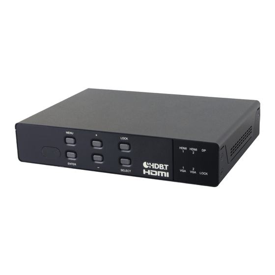
- Page 1 CSC-103TXPL HDMI/DP/VGA to HDMI/HDBaseT Scaler Operation Manual Operation Manual...
- Page 3 DISCLAIMERS The information in this manual has been carefully checked and is believed to be accurate. Cypress Technology assumes no responsibility for any infringements of patents or other rights of third parties which may result from its use. Cypress Technology assumes no responsibility for any inaccuracies that may be contained in this document.
- Page 4 SAFETY PRECAUTIONS Please read all instructions before attempting to unpack, install or operate this equipment and before connecting the power supply. Please keep the following in mind as you unpack and install this equipment: • Always follow basic safety precautions to reduce the risk of fire, electrical shock and injury to persons.
-
Page 5: Table Of Contents
CONTENTS 1. Introduction ............1 2. Applications .............1 3. Package Contents ..........1 4. System Requirements ........2 5. Features ............2 6. Operation Controls and Functions ....3 6.1 Front Panel ..........3 6.2 Rear Panel ..........4 6.3 Remote Control ......... 6 6.4 OSD Menu ..........6 6.5 IR Cable Pin Assignment...... -
Page 6: Introduction
1. INTRODUCTION This HDMI/DP/HDBaseT to HDMI/HDBaseT Scaler supports five inputs including HDMI, VGA, and DisplayPort. Any selected source will be scaled to your preferred resolution for output over HDMI and HDBaseT. HD resolutions up to 1080p@60Hz are supported. This unit also provides audio application flexibility by including multiple unbalanced audio inputs, a 1/4”... -
Page 7: System Requirements
• 1×Operation Manual 4. SYSTEM REQUIREMENTS • Source equipment such as media players, video game consoles, PCs, or set-top boxes. • HDMI receiving equipment such as HDTVs, monitors or audio amplifiers and/or a compatible HDBaseT Receiver with 24V PoC support. •... -
Page 8: Operation Controls And Functions
• Remote control provides discrete input source selection • Supports control via WebGUI, Telnet, IR remote and RS-232 6. OPERATION CONTROLS AND FUNCTIONS 6.1 Front Panel MENU LOCK HDMI HDMI LOCK ENTER SELECT POWER LED: This LED will illuminate to indicate the unit is on and receiving power. -
Page 9: Rear Panel
6.2 Rear Panel 9 10 11 PHANTOM C 1 2 3 4 5 LINE OUT SERVICE MIC IN LINE IN PC 1 PC 2 IR OUT IR IN RS232 INPUT CONTROL COM PORT CONTROL DC 24V HDMI 1 HDMI 2 DISPLAY PORT PC 1 PC 2... - Page 10 IR OUT: Connect to the provided IR Blaster to transmit IR signals to devices within direct line-of-sight of the IR Blaster. IR IN: Connect to the provided IR Extender to extend the IR control range of remotely located devices. Ensure that the remote being used is within direct line-of-sight of the IR Extender.
-
Page 11: Remote Control
6.3 Remote Control HDMI 1~2, DP & PC 1~2: Press any of HDMI1 HDMI2 these buttons to switch immediately to the corresponding input. MENU: Access the OSD menu. EXIT: Exit the OSD menu. EXIT MENU ▲/▼: Navigate up/down within the OSD menu items. - Page 12 LEVEL 1 LEVEL 2 LEVEL 3 LEVEL 4 DISPLAY (cont.) RESOLUTION 640×480 800×600 1024×768 1280×768 1360×768 1280×720 1280×800 1280×1024 1440×900 1400×1050 1680×1050 1600×1200 1920×1080 1920×1200 720×480P 1280×720P60 RESOLUTION 1920×1080i60 1920×1080P60 720×576P 1280×720P50 1920×1080i50 1920×1080P50 NATIVE OUT1 NATIVE OUT2 HDCP ON INPUT HDMI1 HDMI2...
- Page 13 LEVEL 1 LEVEL 2 LEVEL 3 LEVEL 4 DISPLAY (cont.) COMP IN PC COMP IN PC1 [Enable YUV support] COMP IN PC2 0~60 (30) PICTURE CONTRAST 0~60 (30) BRIGHTNESS 0~1023 (512) 0~1023 (512) GREEN 0~1023 (512) BLUE 0~60 (30) HUE* 0~60 (30) SATURATION* 0~60 (10)
- Page 14 LEVEL 1 LEVEL 2 LEVEL 3 LEVEL 4 AUDIO (cont.) DELAY 150ms MUTE 0~100 (80) OUTPUT VOLUME AUTOMATIC EMBEDDED HDMI1 AUDIO EMBEDDED ANALOG AUTOMATIC HDMI2 EMBEDDED ANALOG AUTOMATIC EMBEDDED ANALOG 0~100 (100) INPUT VOLUME HDMI1 0~100 (100) HDMI2 0~100 (100) 0~100 (100) INPUT VOLUME 0~100 (100)
- Page 15 LEVEL 1 LEVEL 2 LEVEL 3 LEVEL 4 STATIC MISCELLANY ETHERNET IP MODE (cont.) DHCP IP ADDRESS 0~255 SUBNET 0~255 GATEWAY 0~255 1~65535 (50000) CONTROL PORT MAC ADDRESS NONE EDID SETUP EDID FROM OUT1 OUT2 DEFAULT NONE EDID TO HDMI1 HDMI2 NO/YES EDID COPY...
-
Page 16: Ir Cable Pin Assignment
6.5 IR Cable Pin Assignment IR Blaster Power IR Signal IR Extender IR Signal Power Ground 6.6 RS-232 Protocol UNIT REMOTE CONTROLLER Assignment Assignment ► ◄ Baud Rate: 9600bps Data Bits: 8 Parity: None Flow Control: None Stop Bits: 1... -
Page 17: Rs-232 And Telnet Commands
6.7 RS-232 and Telnet Commands COMMAND DESCRIPTION List all commands. s factory-reset Return to factory default settings. r version Read FW version. r source Read current input source. s source N Set input source. N = 0~4 0=HDMI 1 1=HDMI 2 2=DP 3=PC 1 4=PC 2... - Page 18 COMMAND DESCRIPTION 11=1600×1200 12=1920×1080 13=1920×1200 14=720×480P 15=1280×720P60 16=1920×1080I60 17=1920×1080P60 18=720×576P 19=1280×720P50 20=1920×1080I50 21=1920×1080P50 22=NATIVE OUT1 23=NATIVE OUT2 r size Read output aspect setting. s size N Set output aspect. N = 0~6 1=Full 2=Follow Input 3=Pan Scan 4=Letter Box 5=Under 2 6=Under 1 r hdmi1-hdcp Read HDCP status for HDMI 1.
- Page 19 COMMAND DESCRIPTION s dp-hdcp N Set HDCP mode for DisplayPort. N = 0, 1 0=Enable 1=Disable r contrast Read contrast setting. s contrast N Set contrast. N = 0~60 r brightness Read brightness setting. s brightness N Set brightness. N=0~60 r color-r Read red color level.
- Page 20 COMMAND DESCRIPTION s nr N Set noise reduction level. N = 0~3 0=Off 1=Low 2=Middle 3=High s pc-auto 1 Activate auto size detection function for the PC source. s pc-reset 1 Return to the default settings for the PC source. r pc-h-pos Read horizontal position of PC source.
- Page 21 COMMAND DESCRIPTION r mic-vol Read microphone volume. s mic-vol N Set microphone volume. N = 0~100 r delay Read audio delay setting. s delay N Set audio delay. N = 0~3 0=Off 1=40ms 2=110ms 3=150ms r mute Read audio mute status. s mute N Set audio mute state.
- Page 22 COMMAND DESCRIPTION s dp-audio N Set DisplayPort audio source. N=0~2 0=Automatic 1=Analog 2=Embedded r hdmi1-vol Read HDMI 1 audio volume. s hdmi1-vol N Set HDMI 1 volume. N=0~100 r hdmi2-vol Read HDMI 2 audio volume. s hdmi2-vol N Set HDMI 2 volume. N=0~100 r dp-vol Read DisplayPort audio volume.
- Page 23 COMMAND DESCRIPTION s osd-trans N Set OSD transparency. N=0~100 r osd-display Read OSD display status. s osd-display N Set OSD display mode. N = 0~2 0=Off 1=Info 2=On r mac-addr Read MAC address. r udp Read UDP port. s udp N Set UDP port.
- Page 24 COMMAND DESCRIPTION s auto-sync-off N Set Auto Sync Off mode. N = 0~2 0=Off 1=Fast 2=Slow r auto-input Read auto input mode. s auto-input N Set Auto-Input mode. N = 0, 1 0=Off 1=Scan All r pc1-comp Read PC1 Component input state. s pc1-comp N Set PC1 component support mode.
- Page 25 COMMAND DESCRIPTION s edid-to N Set the EDID copy destination. N = 0~3 0=None 1=HDMI1 2=HDMI2 3=DP r edid-copy Read activity status of the EDID copy. s edid-copy N Set Copy EDID mode. N = 0, 1 0=No 1=Yes Note: Commands will not be executed unless followed by a carriage return.
-
Page 26: Telnet Control
6.8 Telnet Control Before attempting to use Telnet control, please ensure that both the unit and the PC/Laptop are connected to the same active networks. To access Telnet in Windows 7, click on the “Start” menu and type “cmd” in the search field, then press “Enter”. Under Windows XP go to the “Start”... - Page 27 This will connect us to the unit we wish to control. Type “help” to list the available commands. Note: • Commands will not be executed unless followed by a carriage return. Commands are not case-sensitive. • If the IP address is changed then the IP address required for Telnet access will also change accordingly.
-
Page 28: Webgui Control
6.9 WebGUI Control Please enter the IP address displayed on the “Ethernet Settings” menu of the OSD into a web browser to connect to the scaler’s WebGUI. The WebGUI is divided up into multiple sections (Input, Lock, Information, Display, Picture, Audio, Miscellany, and Factory) allowing for all functions of the unit to be viewed and controlled directly. - Page 29 video) signals to be used. • PICTURE: This section provides detailed controls for the output's RGB levels, contrast, and brightness for all input types. Additional controls for hue, saturation, sharpness and noise reduction are provided for digital input signals while H/V position, Phase, Clock and WXGA support is provided for the PC inputs.
-
Page 30: Connection Diagram
7. CONNECTION DIAGRAM Trigger Control Display Display Source Source Screen Volume Screen Volume Down Down Keypad RS-232 RS-232 Equipped Microphone PC/Laptop Input RS-232 Control System Analog Stereo CD Player Input RS-232 Set-top Box DVD/Blu-ray Internet Power PHANTOM Player C 1 2 3 4 5 Enabled SERVICE LINE OUT... -
Page 31: Specifications
8. SPECIFICATIONS 8.1 Technical Specifications Video Bandwidth 340MHz/10.2Gbps Input Ports 2×HDMI 1×DisplayPort 2×VGA (15-pin D-sub) 1×Microphone Audio (6.35mm) 3×Stereo Audio (3.5mm) 1×IR Extender (3.5mm) Output Ports 1×HDMI 1×Cat.5e/6/7 1×Stereo Audio (3.5mm) 1×IR Blaster (3.5mm) 1×RS-232 (3.5mm) Control Interfaces 1×IP Control (RJ45) 1×RS-232 (9-pin D-sub) 1×Relay (6-pin Terminal Block) Supported Resolutions... -
Page 32: Video Specifications
Dimensions 219mm×43mm×156mm (W×H×D) [Case Only] 219mm×51mm×164.3mm (W×H×D) [All Inclusive] Weight 1,256g Chassis Material Metal Silkscreen Color Black Operating Temperature 0˚C - 40˚C/32˚F - 104˚F Storage Temperature −20˚C - 60˚C/−4˚F - 140˚F Relative Humidity 20 - 90% RH (Non-condensing) Power Consumption 16W/22W (with PoC Receiver connected) 8.2 Video Specifications Supported PC Resolutions (Hz) - Page 33 Supported PC Resolutions (Hz) Input Output 1280×800@60 1280×1024@60 1360×768@60 1366×768@60 1400×1050@60 1440×900@60 1600×900@60 1600×1200@60 1680×1050@60 1920×1080@60 1920×1200@60 (RB) Supported TV Resolutions (Hz) Input Output 720×576i@50...
-
Page 34: Hdbaset Specifications
Supported TV Resolutions (Hz) Input Output 1920×1080p@23.97 1920×1080p@24 1920×1080p@25 1920×1080p@29.97 1920×1080p@30 8.3 HDBaseT Specifications Features Transmitter Audio/Video Control (IR & RS-232) Power to compatible RX unit Power from compatible TX unit ... -
Page 35: Acronyms
9. ACRONYMS ACRONYM COMPLETE TERM Cat.5e Category 5 (enhanced) Cable Cat.6 Category 6 Cable Cat.7 Category 7 Cable Command Line Interface DisplayPort Digital Visual Interface EDID Extended Display Identification Data Graphical User Interface High-Definition HDCP High-bandwidth Digital Content Protection HDMI High-Definition Multimedia Interface HTTP HyperText Transfer Protocol... - Page 36 CYPRESS TECHNOLOGY CO., LTD. www.cypress.com.tw...
Need help?
Do you have a question about the CSC-103TXPL and is the answer not in the manual?
Questions and answers