Table of Contents
Advertisement
Quick Links
Advertisement
Table of Contents

Related Manuals for CYP CSC-5501


Summary of Contents for CYP CSC-5501
- Page 1 CSC-5501 HDMI/DP/VGA to Dual HDMI Scaler Operation Manual Operation Manual...
- Page 3 DISCLAIMERS The information in this manual has been carefully checked and is believed to be accurate. Cypress Technology assumes no responsibility for any infringements of patents or other rights of third parties which may result from its use. Cypress Technology assumes no responsibility for any inaccuracies that may be contained in this document.
- Page 4 SAFETY PRECAUTIONS Please read all instructions before attempting to unpack, install or operate this equipment and before connecting the power supply. Please keep the following in mind as you unpack and install this equipment: • Always follow basic safety precautions to reduce the risk of fire, electrical shock and injury to persons.
-
Page 5: Table Of Contents
CONTENTS 1. Introduction ............1 2. Applications .............1 3. Package Contents ..........1 4. System Requirements ........2 5. Features ............2 6. Operation Controls and Functions ....3 6.1 Front Panel ..........3 6.2 Rear Panel ..........4 6.3 Remote Control ......... 5 6.4 OSD Menu ..........6 6.5 WebGUI Control ........ -
Page 6: Introduction
1. INTRODUCTION This Multi-Format Scaler has DisplayPort, HDMI and PC (VGA) inputs which can be freely selected for output at a scaled resolution of the user’s choosing over the mirrored HDMI outputs. This unit also includes breakout analog and digital audio outputs to provide additional playback flexibility. -
Page 7: System Requirements
4. SYSTEM REQUIREMENTS • HDMI, DisplayPort or VGA source equipment such as media players, video game consoles, PCs, or set-top boxes. • HDMI receiving equipment such as HDTVs, monitors or audio amplifiers. • The use of “Premium High Speed HDMI” cables is highly recommended. -
Page 8: Operation Controls And Functions
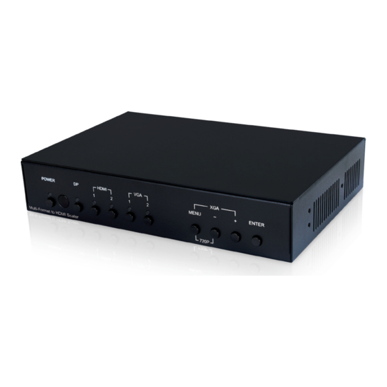
6. OPERATION CONTROLS AND FUNCTIONS 6.1 Front Panel POWER HDMI MENU – ENTER 720P Multi-Format to HDMI Scaler POWER Button & LED: Press this button to power the unit on (Green LED) or place it into stand-by mode (Red LED). IR Window: Accepts IR signals from the included IR remote for control of this unit only. -
Page 9: Rear Panel
6.2 Rear Panel INPUT OUTPUT AUDIO AUDIO COAX AUDIO SERVICE RS-232 CONTROL HDMI HDMI A HDMI B DC 24V DP INPUT Port: Connect to DisplayPort source equipment such as a PC or laptop. Note: In some rare cases, digital DisplayPort audio can’t be supported. -
Page 10: Remote Control
CONTROL Port: Connect directly, or through a network switch, to your PC/laptop to control the unit via Telnet/WebGUI. DC 24V Port: Plug the 24V DC power adapter into this port and connect it to an AC wall outlet for power. 6.3 Remote Control POWER POWER: Press this button to power the unit... -
Page 11: Osd Menu
6.4 OSD Menu All functions of this unit can be controlled by using the OSD (On Screen Display) which is activated by pressing the MENU button on the front of the unit. Use the + (PLUS), − (MINUS), and ENTER buttons to navigate the OSD menu. - Page 12 VIDEO 2ND LEVEL 3RD LEVEL 4TH LEVEL Output 1280×768 60 1360×768 60 1280×720 60 1280×800 60 1280×1024 60 1440×900 60 1400×1050 60 1680×1050 60 1600×1200 60 1920×1080 60 1920×1200 60 720×480p 60 1280×720p 60 1920×1080P 60 720×576p 50 1280×720p 50 1920×1080p 50 1920×1080p 24 1920×1080p 25...
- Page 13 VIDEO 2ND LEVEL 3RD LEVEL 4TH LEVEL DP HDCP Refer To Source REFER TO DISPLAY HDMI1 HDCP Refer To Source REFER TO DISPLAY HDMI2 HDCP Refer To Source REFER TO DISPLAY BLACK No Signal Color White Blue Green Blank Freeze Auto Setup Auto Sync Off 3 Min...
- Page 14 VIDEO 2ND LEVEL 3RD LEVEL 4TH LEVEL Auto Setup Auto Scan From HDMI2 From VGA1 From VGA2 Auto Switch VGA Setup Auto Setup [Current Status] H Position 0 ~ 250 V Position 0 ~ 250 Phase 0 ~ 250 0 ~ 250 (125) Clock Reset 1) Video Routing: Selects the input source to display.
- Page 15 7) No Signal Color: Selects the free run color to use when no live input source is detected. 8) Blank: Allows for the output video and audio to be blanked/ muted. 9) Freeze: Allows for the output video to be frozen. While the output is frozen, audio output will also be muted.
- Page 16 PICTURE 2ND LEVEL 3RD LEVEL 0 ~ 60 (30) Saturation 0 ~ 63 (0) Sharpness Middle High Auto Reset Picture 1) Color Gain R/G/B: These controls provide control over the red, green, and blue color gain level of the scaled output. 2) Color Offset R/G/B: These controls provide control over the red, green, and blue color offset level of the scaled output.
- Page 17 AUDIO 2ND LEVEL 3RD LEVEL FOLLOW VIDEO Audio Routing Audio 1 Audio 2 Audio 3 0 ~ 100 (80) HDMI Volume 0 ~ 100 (80) Coax Volume 0 ~ 100 (80) Analog Volume HDMI Mute Coax Mute Analog Mute Audio Delay 30ms 40ms 50ms...
- Page 18 AUDIO 2ND LEVEL 3RD LEVEL Audio Delay 170ms 180ms 190ms 200ms HDMI Audio Delay Coax Audio Delay Analog Audio Delay Reset Audio 1) Audio Routing: Provides control over the analog audio routing in the unit. Selecting “Follow Video” maps analog audio 1 to all digital inputs (DisplayPort, HDMI 1 &...
- Page 19 Selecting “Off” will disable audio delay for all output types. 9) HDMI Audio Delay: Enable or disable audio delay for the HDMI outputs. 10) Coax Audio Delay: Enable or disable audio delay for the coaxial audio output. 11) Analog Audio Delay: Enable or disable audio delay for the analog audio output.
- Page 20 2ND LEVEL 3RD LEVEL Reset OSD 1) H Position: Set the horizontal position of the OSD menu. 2) V Position: Set the vertical position of the OSD menu. 3) Timer: Set the length of time to wait before automatically turning off the OSD menu if there is no user interaction.
- Page 21 3) Setup Static IP: Manually set the IP address, netmask and gateway address to use when the unit is in Static IP mode. 4) IP: Displays the unit’s current IP address. 5) MAC: Displays the unit’s MAC address. EDID 2ND LEVEL 3RD LEVEL DP EDID 1024×768 60...
- Page 22 EDID 2ND LEVEL 3RD LEVEL 1440×900 60 1400×1050 60 1600×900 60 1600×1200 60 HDMI 1 EDID 1680×1050 60 1920×1200 60 1280×720p 50 1280×720p 60 1920×1080p 50 1920×1080p 60 INT1 User1 User2 User3 Out-HDMI A Out-HDMI B HDMI 2 EDID 1024×768 60 1280×800 60 1280×1024 60 1366×768 60...
- Page 23 EDID 2ND LEVEL 3RD LEVEL 1920×1080p 50 1920×1080p 60 INT1 User1 HDMI 2 EDID User2 User3 Out-HDMI A Out-HDMI B VGA 1 EDID 1024×768 60 1280×800 60 1280×1024 60 1366×768 60 1440×900 60 1400×1050 60 1600×900 60 1600×1200 60 1680×1050 60 1920×1200 60 1280×720p 50 1280×720p 60...
- Page 24 EDID 2ND LEVEL 3RD LEVEL 1366×768 60 1440×900 60 1400×1050 60 1600×900 60 VGA 2 EDID 1600×1200 60 1680×1050 60 1920×1200 60 1280×720p 50 1280×720p 60 1920×1080p 50 1920×1080p 60 INT2 User4 User5 DP EDID Status HDMI1 EDID Status HDMI2 EDID Status [Current EDID Selection] VGA1 EDID Status VGA2 EDID Status...
- Page 25 RESET 2ND LEVEL 3RD LEVEL Reset All Picture Reset All 1) Reset All Picture: Selecting this will reset all picture settings back to their factory defaults. 2) Reset All: Selecting this will reset all of the unit’s settings back to their factory defaults.
-
Page 26: Webgui Control
6.5 WebGUI Control • Application Software Please obtain the “Device Discovery” software from your authorized dealer and save it in a directory where you can easily find it. Connect the unit and your PC/Laptop to the same active network and execute the “Device Discovery” software. Click on “Find Devices on Network”... -
Page 27: Main
• WebGUI Overview After connecting to the WebGUI’s address in a web browser, the login screen will appear. Please enter the appropriate user name and password then click “LOGIN” to log in. Note: The default user name and password is “admin”. 6.6.1 Main Page 0 All primary functions of this unit are controllable via the built-in WebGUI. - Page 28 1) Status: This section provides information about the unit’s current input, output and HDCP status as well as the current Firmware Revision. 2) Video: This section allows for control of input selection, output resolution, aspect ratio, HDCP behavior for the HDMI & DisplayPort inputs, the “no signal”...
-
Page 29: Main
6.6.2 Main Page 1 Select the “MainPage1” tab to adjust settings related to audio output, the OSD, Ethernet, and power. System reset, authentication changes and firmware updates may also be performed from here. If desired, the numerical value for many of the items can be entered directly by typing it in the box above the slider bar. - Page 30 changes to this section, please click the “SAVE” button. Note: If the IP address is changed then the IP address required for WebGUI or Telnet access will also change accordingly. Consult the OSD to view the current IP settings if necessary. 6) FW Update: This section allows for new firmware to be uploaded into the unit.
-
Page 31: Rs-232 Control
6.6 RS-232 Control Serial Port Default Settings Baud Rate 115200 Data Bits Parity Bit None Stop Bits Flow Control None 6.7 Telnet Control Before attempting to use Telnet control, please ensure that both the unit and the PC are connected to the same active networks. To Access the Command Line Interface (CLI) Click Start, type “cmd”... -
Page 32: Rs-232 And Telnet Commands
6.8 RS-232 and Telnet Commands COMMAND Description and Parameters ? Show the full command list. help Show the full command list. get N1 ? Show details about a specific command. N1 = {Base Command String} set system reboot Reboot the unit. set system default... - Page 33 COMMAND Description and Parameters set ip mode N1 Set the IP address assignment mode. Available values for N1: [Static IP mode] [DHCP mode] get ip mode Show the current IP mode. set ip addr N1 Set the static IP address. N1 = X.X.X.X [X = 0 ~ 255] get ip addr...
- Page 34 COMMAND Description and Parameters set int edid 1 to input N1 Assign Internal EDID 1 to input N1. Available values for N1: [DisplayPort] [HDMI 1] [HDMI 2] [All 3 digital inputs] set int edid 2 to input N1 Assign Internal EDID 2 to input N1. Available values for N1: [VGA 1] [VGA 2]...
- Page 35 COMMAND Description and Parameters Available values for N2: [DisplayPort] [HDMI 1] [HDMI 2] [VGA 1] [VGA 2] [All inputs] set user edid N1 to input N2 Assign User EDID N1 to input N2. Available values for N1: [User EDID 1] [User EDID 2] [User EDID 3] [User EDID 4]...
- Page 36 COMMAND Description and Parameters set sink edid [N1] to input N2 Assign output N1’s EDID to input N2. Available values for N1: [HDMI output A] [HDMI output B] Available values for N2: [DisplayPort] [HDMI 1] [HDMI 2] [All digital inputs] get sink edid [N1] data...
- Page 37 COMMAND Description and Parameters get input N1 hdcp mode Show the HDCP handling method currently used by input N1. Available values for N1: [DisplayPort] [HDMI 1] [HDMI 2] set audio route N1 Set the audio routing method. Available values for N1: [Follow video] [Analog audio 1] [Analog audio 2]...
- Page 38 COMMAND Description and Parameters set audio all mute N1 Enable or disable audio muting for all output types. Available values for N1: [Off] [On] set audio [N1] volume N2 Set the audio volume for output type N1. Available values for N1: [HDMI] [Coaxial] [Analog audio]...
- Page 39 COMMAND Description and Parameters set audio delay N1 Set the global audio delay setting. Available values for N1: [Off] [30ms] [40ms] [50ms] [60ms] [70ms] [80ms] [90ms] [100ms] [110ms] [120ms] [130ms] [140ms] [150ms] [160ms] [170ms] [180ms] [190ms] [200ms] get audio delay Show the current global audio delay setting.
- Page 40 COMMAND Description and Parameters get audio [N1] delay enable Show the current audio delay setting for output type N1. Available values for N1: [HDMI] [Coaxial] [Analog audio] set scaler [A] input source N1 Select the input source. Available values for N1: [DisplayPort] [HDMI 1] [HDMI 2]...
- Page 41 COMMAND Description and Parameters set scaler [A] output timing N1 Set the scaled output resolution. Available values for N1: [Native - HDMI A] [Native - HDMI B] [640×480@60Hz] [800×600@60Hz] [1024×768@60Hz] [1280×768@60Hz] [1360×768@60Hz] [1280×720@60Hz] [1280×800@60Hz] [1280×1024@60Hz] [1440×900@60Hz] [1400×1050@60Hz] [1680×1050@60Hz] [1600×1200@60Hz] [1920×1080@60Hz] [1920×1200@60Hz] [720×480p@60Hz] [1280×720p@60Hz]...
- Page 42 COMMAND Description and Parameters set scaler [A] aspect ratio N1 Set the output aspect ratio. Available values for N1: [Overscan] [Full] [Best fit] [Pan & scan] [Letterbox] [Underscan 2] [Underscan 1] [Follow input] get scaler [A] aspect ratio Show the current output aspect ratio. set scaler [A] auto sync off N1...
- Page 43 COMMAND Description and Parameters get scaler [A] no signal color Show the currently selected free run color. set scaler [A] blank N1 Enable or disable blanking the video/audio output. Available values for N1: [Off] [On] Note: When enabled, sync will continue to be sent with the black screen.
- Page 44 COMMAND Description and Parameters get input auto scan Show the current auto scan setting. set input auto switch N1 Enable or disable the auto input switch function. Available values for N1: [Off] [On] get input auto switch Show the current auto input switch setting. set input N1 vga auto...
- Page 45 COMMAND Description and Parameters get input N1 vga h position Show the current horizontal position of input N1. Available values for N1: [VGA 1] [VGA 2] set input N1 vga v position N2 Set the vertical position for input N1 (VGA inputs only). Available values for N1: [VGA 1] [VGA 2]...
- Page 46 COMMAND Description and Parameters set input N1 vga clock N2 Set the clock for input N1 (VGA inputs only). Available values for N1: [VGA 1] [VGA 2] N2 = 0 ~ 250 [Clock] get input N1 vga clock Show the current clock of input N1. Available values for N1: [VGA 1] [VGA 2]...
- Page 47 COMMAND Description and Parameters set scaler [A] osd timeout N1 Set the OSD menu timeout length, or disable the timeout. Available values for N1: [Off] [5 seconds] [10 seconds] [15 seconds] [20 seconds] [25 seconds] [30 seconds] [35 seconds] [40 seconds] [45 seconds] [50 seconds] [55 seconds]...
- Page 48 COMMAND Description and Parameters set scaler [A] r gain N1 Set the output’s red gain level. N1 = 0 ~ 1023 [Red gain] get scaler [A] r gain Show the current red gain output level. set scaler [A] g gain N1 Set the output’s green gain level.
- Page 49 COMMAND Description and Parameters get scaler [A] b offset Show the current blue offset output level. set scaler [A] brightness N1 Set the output’s brightness level. N1 = 0 ~ 60 [Brightness] get scaler [A] brightness Show the output’s current brightness level. set scaler [A] contrast N1...
- Page 50 COMMAND Description and Parameters set scaler [A] nr N1 Set the amount of noise reduction to apply to the output. Available values for N1: [Off] [Low] [Middle] [High] [Auto] get scaler [A] nr Show the current noise reduction setting. Note 1: Commands will not be executed unless followed by a carriage return.
-
Page 51: Connection Diagram
7. CONNECTION DIAGRAM RS-232 Equipped Network Switch RS-232 Power Supply INPUT OUTPUT AUDIO AUDIO COAX AUDIO SERVICE RS-232 CONTROL DC 24V HDMI HDMI A HDMI B DisplayPort Input S/PDIF Output AV Receiver Media Player HDMI Input HDMI & Stereo HDMI & Stereo Media Player Inputs Outputs... -
Page 52: Specifications
8. SPECIFICATIONS 8.1 Technical Specifications Input Bandwidth 165MHz/4.95Gbps Input Ports 1×DisplayPort 2×HDMI 2×VGA (HD-15) 3×Analog Stereo (3.5mm) Output Ports 2×HDMI 1×Digital S/PDIF (RCA) 2×Analog Stereo (3.5mm) Control Ports 1×RS-232 (DE-9) 1×LAN (RJ-45) Baud Rate 115200 Power Supply 24V/2.7A DC (US/EU standards, CE/FCC/UL certified) ESD Protection Human Body Model: ±8kV (Air Discharge) -
Page 53: Video Specifications
8.2 Video Specifications Input Output Scaled Supported Resolutions (Hz) HDMI HDMI 720×400@85 720×480i@60 720×480p@60 640×480@60/72/75/85 720×576i@50 720×576p@50 800×600@56/60/72/75/85 ... -
Page 54: Audio Specifications
8.3 Audio Specifications Analog Input Max Audio Level 2Vrms Impedance <100kΩ Type Unbalanced Analog Output Max Audio Level 2Vrms THD+N < −60dB@0dBFS 1kHz (A-wt) > 70dB@0dBFS Frequency Response < ±3dB@20Hz~20kHz Crosstalk < −60dB@10kHz Impedance 470Ω Type Unbalanced HDMI Input/Output LPCM Max Channels 2 Channels Sampling Rate (kHz) -
Page 55: Cable Specifications
8.4 Cable Specifications 1080p Cable Length 8-bit High Speed HDMI Cable HDMI Input HDMI Output DisplayPort Cable DisplayPort Input... -
Page 56: Acronyms
9. ACRONYMS ACRONYM COMPLETE TERM Analog-to-Digital Converter ASCII American Standard Code for Information Audio/Video Command-Line Interface COAX Coaxial Digital-to-Analog Converter DHCP Dynamic Host Configuration Protocol DisplayPort Digital Visual Interface EDID Extended Display Identification Data Graphical User Interface High-Definition HDCP High-bandwidth Digital Content Protection HDMI High-Definition Multimedia Interface HDTV... - Page 57 ACRONYM COMPLETE TERM Video Graphics Array WUXGA (RB) Widescreen Ultra Extended Graphics Array (Reduced Blanking) Extended Graphics Array...
- Page 60 CYPRESS TECHNOLOGY CO., LTD. www.cypress.com.tw...
Need help?
Do you have a question about the CSC-5501 and is the answer not in the manual?
Questions and answers