
Related Manuals for Digimerge DGR204


Summary of Contents for Digimerge DGR204
-
Page 1: Digital Video Recorder
Four Channel Networkable Digital Video Recorder Model: DGR204 Installation / User Manual Digimerge Technologies Inc. -
Page 2: Safety Precautions
SAFETY PRECAUTIONS All the following safety and operated instructions which will prevent harm or damage to the operator and other persons should be read before the unit is operated. WARNING To reduce the risk of fire or electric shock, do not expose this appliance to rain or moisture. Do not block ventilation openings. -
Page 3: Table Of Contents
Table Of Contents 1. PRODUCT FEATURES ... 5 1.1 Product Introduction ...5 1.2 Product Features...5 2. DESCRIPTION OF THE FRONT/REAR VIEW ... 6 2.1 Front View ...6 2.2 Rear View ...9 2.3 ALARM In/Out ...10 3. INSTALLATION ... 11 3.1 Basic Connection ... 11 3.2 Hard-Disk Drive Installation ...12 3.3 System Information and channel selection...13 3.4 Updating System Software ...15... - Page 4 10.2 The Image Viewer...64 11. INDEX TABLE ... 65 12. NETWORK CONFIGURATION ... 66 12.1 Cable Connections ...66 12.2 Configure Your DVR Network Settings ...67 12.3 TCP/IP Communication Software...69 12.4 TCP/IP installation ...71 12.5 TCP/IP Configuration setting ...71 12.6 Connection Testing...72 13.
-
Page 5: Product Features
1. PRODUCT FEATURES 1.1 Product Introduction The DGR204 four channel Digital Video Recorder (DVR) provides high quality storage of up to four video sources. Equipped with a range of comprehensive features, such as video motion detection, pre-alarm recording, thumbnail search, jog/shuttle function, hard drive expansion, and TCP/IP connectivity, this DVR will make your applications far more flexible and effective than ever before. -
Page 6: Description Of The Front/Rear View
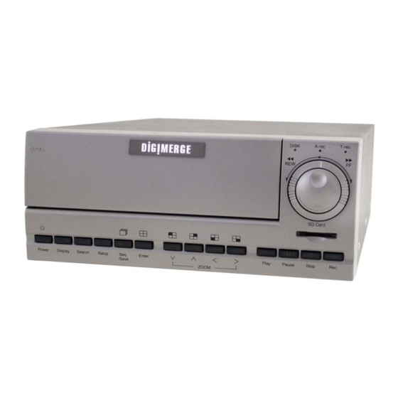
2. DESCRIPTION OF THE FRONT/REAR VIEW 2.1 Front View Power Display Search Setup Seq. /Save Hard-disk drive compartment. This compartment houses the removable (hot-swappable) hard disk drive. NOTE: The compartment must be locked before the hard drive can be used. Hard disk compartment lock: The key lock secures a hard disk in place. - Page 7 the unit off. DISPLAY button: Press to show the system operation status on the screen. (See Section 3.3 for Display indications) Setup button: Press this to enter the setup menu. Press again to exit the setup mode. Search button: Press the SEARCH to enter the search mode to access recorded video. Left / Right (CH1 / CH2 ) buttons: In setup menu/ search mode, use these buttons scroll Left/Right to select desired items in the menu setup mode.
- Page 8 Jog Dial: The Jog Dial can be used to step frame by frame in the forward or reverse direction. SD CARD Slot: This is used for system software updating and archiving/accessing critical images. Mobile Rack Power LED: Indicates the power status of the Mobile Rack. The green light indicates the Mobile Rack is activate.
-
Page 9: Rear View
AUDIO OUT: This provides the unit’s audio signal to a speaker. AUDIO IN Connector: This connector is used to connect the audio output from a camera or other devices to the DVR. ETHERNET 10/100 Connector: This is one standard RJ-45 connector for 10/100 Mbps Ethernet networks. -
Page 10: Alarm In/Out
2.3 ALARM In/Out ALARM RESET RECORD IN ALARM1 IN ALARM2 IN THIS FIGURE IS LOOKED FROM THE REAR VIEW GND: Ground Contact. ALARM OUT (OUTPUT): This is a common alarm output trigger. Connect this to external devices such as buzzers or lights. Switches Low (GND) ( DISK FULL (OUTPUT): This is a disk full output trigger. -
Page 11: Installation
Camera Camera MONITOR AUDIO Monitor ATTACHING AN EXTERNAL DEVICE TO DVR Connect an alarm out, alarm input, and a peripheral device as shown in the diagram below. Alarm In -> Alarm1 In, Alarm2 In, Alarm3 In, Alarm4 In hi-z RS-485... -
Page 12: Hard-Disk Drive Installation
3.2 Hard-Disk Drive Installation The DVR is capable of supporting two hard drives - One internal drive (from factory) and one hot swappable mobile drive (factory option). The internal HDD (compartment HD1), is default-configured as a master. If adding an additional HDD to the Mobile Rack (compartment HD2), please set to Master and follow the install instructions in section . -
Page 13: System Information And Channel Selection
09- 05-2003 16:13:02 ( System Data/ Time ) Press the Display button once; the DVR will display the following sample message plus the default display. Press the Display button button one more time to back to the default display. again; the unit will not display any OSD message. Press the... - Page 14 Figure 3.3 A. 1+ 2: 59G 12.4 HR QUALITY: BEST NTSC RATE: 6 HR 10 F/S HD P SIZE 20 G 39.5% P 39 G 0.0% R IP : 192 . 168 . 1 . 90 3.3.2 Channel Selection The CH1, CH2, CH3, CH4, Quad ( channels and zoom in factor.
-
Page 15: Updating System Software
3.4 Updating System Software If the system software of the 4CH DVR needs to be upgraded, please take the following steps to safely update it. Important: Before carrying out the following procedures, please ensure the SD card is working and the file of system software is intact 1. -
Page 16: Basic Operations
4. BASIC OPERATIONS This section outlines the basic operating instructions for the DGR204. 4.1 Configuring Recording Settings Recording Time settings (Recording Rate and Picture Quality Setting) Recording time will vary depending on the image size, recording rate, and the capacity of the hard-disk drives. - Page 17 NOTE 1: Recording times on the tables above are estimated. For actual available recording time of a recording configuration, please refer to the system information of the DVR. (Please refer to section 3.3 system information for more details.) 2: No audio function at the refresh rate in NTSC: 30 frame/sec ~ 15 frame/sec, 1/8 frame/sec ~ 1/16 frame/sec.
-
Page 18: Recording Operations
(3) To access just recorded video, please refer to section 4.4 for more details. 4.2.2 Timer Recording Timer recording provides two periods of time each day in a weekly table which programs the DVR Start and Stop recording at specified times. Please take the following steps to program the scheduled recording. - Page 19 NOTE: If a programmed schedule falls within the current set time of the DVR, recording will begin upon exiting programming. NOTE: If you activate the recording function before the scheduled recording, the unit will operate recording as shown in the diagram below and keep those Images in different files.
- Page 20 MAIN MENU RECORD ALARM TIMER/ SEQ/ TITLE COMMUNICATION DISK SYSTEM GOTO TIMER/SEQ/TITLE PAGE TIMER/ SEQ/ TITLE CLOCK : SET REC ENABLE : OFF TIMER : SET SEQUENCER : SET TITLE : SET MAIN PAGE SET REC SCHEDULE REC SCHEDULE START END START END S : 00:00-00:00 00:00-00:00...
- Page 21 4.2.3 Alarm Recording Take the following steps to activate the programmed alarm recording. For ALM OPERATION, REC RATE, REC QUALITY, AUDIO, ALM TYPE, ALM DURATION, and PRE-ALARM settings, please refer to section 5.2 for more details. (1) Press the Setup button (2) Select ALARM and press the Enter button (3) Set the desired REC RATE, REC QUALITY, ALM TYPE, and ALM DURATION for use.
-
Page 22: Externally Triggered Recording
4.2.4 Externally triggered Recording By connecting the RECORD IN of ALARM I/O on the rear panel of the DVR, you can activate/deactivate the recording function of a DVR. The file will be kept with a prefixed “R”. Please refer to section 2.3 for more details. -
Page 23: Playback Operations
This section outlines the controls and options available during playback of recorded video. When playing a file, the monitor should display a flashing PLAY message and the PLAY button up indicating that the DVR is in the playback status. To switch between channel 1..4 and quad view in the playback mode, please press... -
Page 24: Playback Picture-By-Picture
There are 4 speeds available for a slow playback: 1/2, 1/4, 1/8, 1/16. While playing back recorded video at the recorded speed: (1) Press the PAUSE button (2) Forward: Turn the Shuttle dial direction at a speed slower than the recorded speed. Each subsequent turn of the shuttle to the right increases the forward rate, as 1/2, 1/4, 1/8, and 1/16. - Page 25 4.4.1 Full List Search Take the following steps to proceed with the full-list search function. (1) Press the Search button (2) Select the FULL LIST and press the Enter button video. (3) Highlight the specific recorded video of your requirement and press the Enter button display the selected video.
-
Page 26: Time Search
4.4.3 TIME Search Take the following steps to proceed with the time-list search function. (1) Press the Search button (2) Select the TIME SEARCH and press the Enter button (3) Set the time period you wish to search for the recorded video. (4) Press the Enter button to start searching and displaying the concerned image. - Page 27 Setup button (6) Once reaching the critical point at any level, the user can start playback by just clicking the PLAY button SEARCH FULL LIST ALARM LIST TIME SEARCH THUMBNAIL SD CARD 4.4.5 SD CARD Search Take the following steps to proceed with the SD card search function. (1) Insert a SD Card into the SD card slot of the rear unit.
-
Page 28: Backup Operations
4.5 Backup Operations 4.5.1 Mobile Rack HD Backup Operations There are three ways available to duplicate the recorded video from HD 1 (Fixed HD) to HD 2 (Mobile Rack HD). Please take the following steps to proceed. (1) Set HD 2 to BACKUP first. Take the following steps. Press the Setup button Highlight DISK and press the Enter button Then set HD 2 USAGE to BACKUP. - Page 29 MAIN MENU RECORD ALARM TIMER/ SEQ/ TITLE COMMUNICATION DISK SYSTEM GOTO DISK PAGE SELECT: Duplicate a particular recorded video from HD1 to HD2. Stay on the DISK SETTING page. Use the “ ” and “v” press the Enter button to list all the recorded video. Press the “...
-
Page 30: Security Digital Card (Sd Card) Backup Operations
Backup the System setting info into SD Card. The 4CH DVR offers a quick setup method by using a SD card. If a user wants to set many 4CH DVR devices with the same settings, the 4CH DVR could save the whole setting in the SD card, then transfer it to another DVR. -
Page 31: Key Lock Operation
MAIN MENU RECORD ALARM TIMER/ SEQ/ TITLE COMMUNICATION DISK SYSTEM GOTO SYSTEM SETTING Updating System Software (Please refer to section 3.4 for more details.) 4.6 Key Lock Operation The Key lock operation protects the unit against unauthorized use by disabling the entire front panel controls. -
Page 32: Menu Setup
5. MENU SETUP There are 6 categories of operation settings able to be configured from the setup menu. The following sections will provide step-by-step instructions for configuring/changing the setup options. Press the Setup button to access the setup menu. Once inside the menu system, the on-screen menu allows you to set up the key features of the unit. -
Page 33: Rec Setting
PAL unit) resolution REC QUALITY: This option determines the image quality to be recorded. The DVR stores images in the compressed format and allows the image quality to be altered by the image size. There are 4 levels of image quality you can select from: BEST, HIGH, STANDARD, and BASIC. Selecting the BEST image for use provides higher-resolution recorded images, and normally takes up more storage space than a HIGH, STANDARD or BASIC image does. -
Page 34: Alarm Setting
NOTE: Audio function can only be activated in the following refresh rate in NTSC(PAL): 10(8.3), 6(5), 2.7(2.7), 1.2(1.4), 0.61(0.76), 0.35(0.44) frames/sec 5.2 ALARM SETTING This menu allows users to program the configuration of alarm recording only when an alarm input is activated. -
Page 35: Motion Setting
OFF: Disables AUDIO recording. NOTE: Audio function can only be activated in the following refresh rate in NTSC(PAL): 10(8.3), 6(5), 2.7(2.7), 1.2(1.4), 0.61(0.76), 0.35(0.44) frames/sec ALM TYPE: This option allows users to set a type of alarm input corresponding to the sensor signal in use. NO: Normally Open. - Page 36 would trigger the alarm recording. Before using the motion detection function, please turn the CH1/ CH2/ CH3/ CH4 options as ON, and set the SENTIVITY (1 ~ 5 ) to a suitable value. SENSITIVITY MAIN PAGE ENABLE MOTION DETECTION CH1/ CH2/ CH3/ CH4 : These options enables/disables the motion detection.
-
Page 37: Timer/ Seq/ Title
The DVR provides a weekly table, consisting of two periods of time each day for scheduled recording. This option allows you to set the time each day that the DVR will start and stop recording. The SEQUENCER setting allow user to set the sequence dwell time (time interval ) for each channel, and TITLE setting allow user to set TITLE for each channel. - Page 38 view( ), the valid values are 01 ~ 99 seconds, set to 00 would disable the corresponding channels during the sequential jumping is proceed. In live mode, press the Seq./Save button to switch the screen to the sequential jumping mode. SEQUENCER CHANNEL 1 DWELL...
-
Page 39: Communication
GOTO COMM PAGE COMM ID: Communication ID for RS232 and RS485 communication. After the 4CH DVR receives a RS232 or RS485 command, it checks if the <Dest ID> within the code is the same as the COMM ID, in which case the particular command can be accept. - Page 40 OFF: Disables it. ON: Enables it. NOTE: If provided with a DHCP server, the 4CH DVR can get an IP automatically by setting this option to ON. NET IP: This option is used to configure the Ethernet communication settings. This is required for the purpose of making a network connection.
- Page 41 FTP connection. Please consult with a qualified MIS professional to configure it. FTP ACCOUNT FTP IP : 192.168.001.128 USER : [ dvr PASSWORD : [ 00000000 PATH : [ /dvrvideo FTP IP : Every FTP server has to own an IP address to be identified on the network. Input the IP address of the FTP server.
-
Page 42: Disk Setting
5.5 DISK SETTING MAIN MENU RECORD ALARM TIMER/ SEQ/ TITLE COMMUNICATION DISK SYSTEM GOTO DISK PAGE REFORMAT: This option allows you to clear out all the data in the hard-disk drive. You will be required to enter the pre-set password before proceeding with clearing out the data. Enter the standard password “9999” if you don’t set your individual password. -
Page 43: System
5.6 SYSTEM This section is used for accessing the history of the operation status, setting the password, resuming factory default, and determining the menu display background. MAIN MENU RECORD ALARM TIMER/ SEQ/ TITLE COMMUNICATION DISK SYSTEM GOTO SYSTEM SETTING OPERATION LOG: This log shows the history of the operation status in chronological order. - Page 44 There are 3 levels of background color transparency, you can choose from : level 1 is totally transparent, level 3 is opaque, and level 2 is between level 1 and 3. The background color is used in setup menu and search function. BUZZER: This option determines the embedded buzzer sounding a tone to signal the following situations.
- Page 45 The 4CH DVR offers a quick setup method by using a SD card. If the user wants to set up many a number of the same devices with the same settings, he can save the whole settings to a SD card, then transfer to another DVR.
-
Page 46: Rs-232 & Rs-485 Protocol
6.1.1 Use a Null Modem cable (the standard RS-232 9 Pin Cable with Pin 2 and Pin 3 exchanged, see pin configuration chart below for details) to connect the COM 1 on the rear panel of the DVR to a PC. - Page 47 The different command types and their corresponding parameters are as follows: 6.2.1 Keys and signals PC Send: <0x41>, <0x01>, <0x20>, <0x01>, <Key Value>, <0x4f> < The value of a specific front panel key > KEY_PLAY KEY_STOP KEY_PAUSE KEY_POWER KEY_REC KEY_SETUP KEY_ENTER KEY_SEARCH KEY_DISPLAY...
- Page 48 < 6 bytes Date/Time >, = year(2 bytes, =LowByte + HighByte*256), month ( 1 byte), day (1 byte), hour(1 byte),min(1 byte) Example: to search 06/12/2003 17:00 the Date/Time = <0xd3>,<0x07><0x06>,<0x0b>,<0x11>,<0x00> where 2003= 210(=0xd3) + 7(=0x07) *256 NOTE: The DVR accepts RS-232 time search commands only under the live or playback Mode.
-
Page 49: Ide Hard Disk Installation
7. IDE Hard Disk Installation Usually, the unit comes with one hard-disk drive installed in compartment HD 1, which is default-configured as a master. Please note that both drives should be configured as 'Master'. To install an additional HDD in the HD2 Mobile Rack, please follow the steps below. - Page 50 4. Setting the jumper of your hard disk driver. The way to set the jumper of the drive varies between manufacturers; please refer to the instructions on the driver to set the jumpers in the master position. 5. Attach the interface connector and the power connector to the drive. Please note the red lining of the IDE cable and the red wire of power cable must line up side by side.
- Page 51 9. Push the carrier body further into the mobile rack until fully inserted. 10. Push the active-handle inward. 11. Lock the Key.
-
Page 52: System Default
8. System Default MAIN MENU RECORD ALARM TIMER/ SEQ/ TITLE COMMUNICATION DISK SYSTEM GOTO REC PAGE MAIN MENU RECORD ALARM TIMER/ SEQ/ TITLE COMMUNICATION DISK SYSTEM GOTO ALARM PAGE MAIN MENU RECORD ALARM TIMER/ SEQ/ TITLE COMMUNICATION DISK SYSTEM GOTO CLOCK / TIMER PAGE REC SETTING REC RATE : 10 F/S... - Page 53 MAIN MENU RECORD ALARM TIMER/ SEQ/ TITLE COMMUNICATION DISK SYSTEM GOTO COMM PAGE MAIN MENU RECORD ALARM TIMER/ SEQ/ TITLE COMMUNICATION DISK SYSTEM GOTO DISK PAGE MAIN MENU RECORD ALARM TIMER/ SEQ/ TITLE COMMUNICATION DISK SYSTEM GOTO SYSTEM SETTING COMM SETTING COMM ID : 01 RS232...
-
Page 54: Message
9. O.S.D. Message O.S.D. Message NO DISK BATTERY LOW LOADING VIDEO LOSS VIDEO IN KEY LOCKED KEY UNLOCKED n1 OF n2 ITEMS PROGRESS n3 % BACKUP COMPLETE HD2 SPACE NOT ENOUGH NO ENTRY FOR BACKUP BACKUP INCOMPLETE NOT FOUND DISK FULL EMPTY SET TO NTSC, PLS RESTART SOFTWARE UPDATE... -
Page 55: Network Viewer And Image Viewer
10.1 The Network Viewer 10.1.1 Introduction to Network Viewer The Network Viewer allows you to potentially access 16 4CH DVR’s from a remote desktop or laptop in a TCP/IP networking environment. It can perform the following functions. View live images from the 4CH DVR Store, search, and review recorded video from the 4CH DVR HDD. - Page 56 Physical specification for Ethernet Wire Type Connector Type Max. Cable Length Hub Wiring Configuration PC Wiring Configuration NOTE: For more details on network connections, please refer to the following document. 10.1.2 Install the Network Viewer in your PC Install the Network Viewer from the supported CD-R. 1.
- Page 57 10.1.3 View the 4CH DVR video from a remote PC 1. Click the Find button to search for all DVR devices connected in the LAN. 2. Choose a channel number from the Channel drop-down list. 3. Type in the user name for the chosen 4CH DVR.
- Page 58 Click to change the settings of a chosen device. Delete Click to remove the connection of a chosen device. Find Click to find the connection of the all 4CH DVR device in the LAN. Connect Click to establish the connection between the devices and the computer. Login Click to access the display page of the Network Viewer.
-
Page 59: Function Buttons
Function Buttons The Split-Screen display function bar. This allows you to display the connected device in the multi-format screens of 1, 2x2, 5+1, 7+1,3x3, 12+1, and 4x4. Press to enter the PC SYSTEM SETUP window, which allows you to program the System Setup, Record Setup, and Alarm Setup. Press to enter the selected device (the Single-device display mode). - Page 60 Function Buttons Playback function bar. Play- Click to a recorded video from the PLAY LIST. Pause- Click to freeze the image. Stop- Click to stop playing back the recorded video or cease recording. REC- Click to activate the recording function of the device.
- Page 61 4CH DVR Status Box. This box indicates the selected device status. PLAY: The device is in the playback mode. LIVE: The device is in the live display mode. WAIT: The device is processing the command. PAUSE: Pauses the image. This allows you to search a recorded video kept in the HDD of the device.
- Page 62 10.1.4 Change the Record & Timer Properties Via the Network Follow the instructions below to reconfigure the record and schedule recording settings via the network. Set the regular record settings 1. When in the single –device mode, click as in A above) 2.
- Page 63 10.1.5 Archive Images to the Computer Playback images can be stored in a local PC in the JPEG format. Follow the instructions below to save the viewed images to your PC. 1. Press to enter the following sample screen whenever in the playback mode. 2.
-
Page 64: The Image Viewer
SD card or HDD of a computer, but also protects an archived image from reproduction or interpolation. If an image isn’t in the original format made by a 4CH DVR, the Image Viewer won’t display the image and instead will send a warning message” Wrong File, Can’t Open”. -
Page 65: Index Table
The following description details how the DVR manages an index table issue. The DVR will generate a time index table indicating recorded data is kept in a particular HDD. This allows to individually selecting recorded data to be displayed via the alarm list search and full list search. -
Page 66: Network Configuration
12. Network Configuration 12.1 Cable Connections Please follow the instructions below to connect your DVR to a computer or a network and to choose a proper RJ-45 cable configuration for connections. Physical specification of RJ-45 cable for Ethernet Wire Type Connector Type Max. -
Page 67: Configure Your Dvr Network Settings
AUDIO ALARM RJ-45 12.2 Configure Your DVR Network Settings Upon network hardware connection, you need to activate the network function and configure the proper network settings of the DVR. 12.2.1 Enable DVR Network Function MAIN MENU RECORD ALARM TIMER/ SEQ/ TITLE... - Page 68 NOTE: This function can only work if the LAN which the unit is connected to has a DHCP server. If the DHCP server is working, the DVR will obtain an IP address automatically from the DHCP server. In that case please skip the section 2.3 (Set IP address) and follow section 3.
-
Page 69: Tcp/Ip Communication Software
NOTE: When only one unit of the DVR is connected to a computer or LAN, you can freely assign an IP address for the DVR. For example, there are a range of DVR IP addresses from 192.168.0.1 to 192.168.0.255. You can pick one for use from the range of the IP. - Page 70 Click the NETWORK icon twice to enter the NETWORK setting windows. Click on the Configuration tag; check if the TCP/IP is included among the network components list. If the TCP/IP is included, please process step 5. If it is not included, please follow step 4 to install the TCP/IP.
-
Page 71: Tcp/Ip Installation
PC will be restarted. 12.5 TCP/IP Configuration setting Click Start Settings Control Panel Select TCP/IP, and then click Properties. Before processing the DVR installation in a WAN, please make sure the Internet connection works properly. If not, please contact your ISP provider. Network. -
Page 72: Connection Testing
If there is no DHCP server, please select specify an IP address and type in the IP address of your PC. This IP address must be different from the DVR IP but in the same class type. NOTE: The IP address of a DVR in a network must be unique to itself as opposed to those of the other chosen PCs, but in the same class type 12.6 Connection Testing... - Page 73 If you receive a response as in the sample screen below, the connection hasn’t been successfully established. Please re-check all the hardware and software installation by repeating steps 1 to 5. If you still can’t establish the connection after rechecking, please contact your dealer.
-
Page 74: Specifications
Operation Temperature Regulation Provided Accessories *Design and specifications subject to change without notice. 4CH DVR NTSC 720 x 576 pixels / 352 x 288 pixels Composite Video In (BNC) x 4 Composite Video Out (BNC) x 4, Monitor Out (BNC) x 1 Line In / Out (RCAx2), 16 bits, 8 kHz >... -
Page 75: Appendix 1. -Scanip
APPENDIX 1. –SCANIP Follow the instructions below to use the SCANIP software to search the DVR devices from a local location. 1. Click the button to discover the connection of the all-type device in the LAN. The Device List will display the connection of the all-type device. - Page 76 Address”, “Gateway Address”, and “NET Mask”. Follow each insertion you make by typing in the “Login Name” and “Password”, and click “UPDATE” to send your alterations to the DVR. 6. Auto search “Free IP Address”. If you clicked “Yes” the “Free IP Address” box will appear on the right.
- Page 77 8. To change any IP address, type in the new address in the “Free IP Address” box on the right as well as the device “Login Name” and “Password” in their respective blanks at bottom left, then click “UPDATE”, and the new address will automatically be sent to the device. 9.
-
Page 78: Limited Warranty
15. Limited Warranty Warranty: Subject to the exclusions and limitations below, Digimerge warrants to the initial end-user purchaser that the product will be free from defects in material and workmanship for a period of one year from the date of purchase. - Page 79 Digimerge Technologies Inc. 300 Alden Road Markham Ontario L3R 4C1 www.digimerge.com rev01...
Need help?
Do you have a question about the DGR204 and is the answer not in the manual?
Questions and answers