
Related Manuals for Digimerge DGN209


Summary of Contents for Digimerge DGN209
-
Page 1: Digital Video Recorder
9 Channel Multiplex Digital Video Recorder Model: DGN209 Installation / User Manual Digimerge Technologies Inc. - Page 2 Under the copyright laws, this documentation may not be copied, photocopied, reproduced, translated, or reduced to any electronic medium or machine-readable form, in whole or part without the prior written consent of Digimerge Technologies Inc., except in the manner described in the documentation.
-
Page 3: Table Of Contents
Table of Contents Important Safety Instructions................................3 Introduction ....................................4 Features .......................................4 System Contents ..................................5 Getting Started .....................................5 Front Panel Controls ..................................6 Back Panel Connections ................................8 Accessing the Main Menu ................................9 Main Menu ....................................9 Search......................................9 Timer Recording Setup ................................11 Record Quality Setup .................................12 Camera Channel Setup................................13 Motion Detection ..................................15 System Setup.....................................17... -
Page 4: Important Safety Instructions
Important Safety Instructions All the safety and operating instructions should be read before operating this equipment. The improper operation may cause irreparable damage to the appliance. Lift and place this equipment gently. Do not expose this equipment to direct sunlight. Do not use this equipment near water or in contact with water. -
Page 5: Introduction
Introduction The DGN209 combines a 9 channel multiplexer with a Digital Video Recorder (DVR). The DVR offers many advantages over traditional time lapse VCR’s, allowing you to quickly access and search for a specific time segment or event, which has been recorded. This high quality recorded video can be viewed at various playback speeds as well as frame-by-frame with the Jog Button feature. -
Page 6: System Contents
System Contents The DGN209 box should include the items listed below. Please take a moment to verify that no items are missing from the package. DGN209 Digital Video Recorder 80 GB Hard Disk Drive is included 2 Keys for Installation / User Manual... -
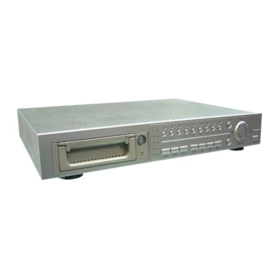
Page 7: Front Panel Controls
Front Panel Controls SLOW SLOW AVC 776 AVC 776 Digital Multiplex Recorder Digital Multiplex Recorder Left Left Right Right MENU MENU ENTER ENTER SELECT SELECT ZOOM ZOOM Down Down POWER POWER 7 8 9 7 8 9 REMOVABLE HDD CARTRIDGE Please refer to Appendix #1. - Page 8 UP: When in the setup mode, it works as an Up directional button. 15. PLAY Press PLAY to playback the most recently recorded video. 16. REW / Left REW: Under DVR play mode, it can play video backward at different speeds. (Press REW again to adjust speed as 1, 2, 4, 8, 16, 32 times) Left: When in the setup mode, it works as Left directional button.
-
Page 9: Back Panel Connections
Back Panel Connections POWER INPUT Connects to the Power cord. EXTERNAL I/O Connects to a PC for Remote Control via RS-232 or to an Alarm Block. (see Appendix #3 for more info) 75/HI When using the LOOP function, allows for HI impedance or 75ohms. VIDEO INPUT (1-9) Connects to a video source (i.e. -
Page 10: Accessing The Main Menu
Search The DGN209 allows you to easily find sections of recorded video using the SEARCH feature. To access the Search option, press MENU followed by the 4 digit password. Use the ▲ / ▼ to scroll to the Search option and press ENTER. -
Page 11: Full List
T 2002-JAN-01 01:02:03 M-HDD D 2002-JAN-01 01:02:03 S-HDD Press ENTER to view a selected piece of video on the list. The DGN209 will play M 2002-JAN-01 01:02:03 S-HDD the video in chronological order, until it hits the End of the list. Playback can be ◄: Page Up ►: Page Down... -
Page 12: Timer Recording Setup
Timer Recording Setup On the Main Menu, selecting the Timer option will allow you to set daily schedules in which (Menu) you would like the DVR to automatically record. Search Pressing ENTER after scrolling to the Timer option will bring up the following menu options: ►Timer Record Camera... -
Page 13: Record Quality Setup
Record Settings On the Main menu, selecting the Record option will allow you to set the quality and speed of (Menu) recordings. Search Timer Pressing ENTER after scrolling to the Record option will bring up the following menu ► Record options: Camera System... -
Page 14: Camera Channel Setup
Motion Trigger Record Press ENTER to confirm MOTION TRIGGER RECORD setup. Press▲ / ▼ to toggle the option between ON and OFF. 1. Select “ON” to set up the motion trigger recording: It can automatically switch from stand-by mode to Recording Mode. The motion detection will change the scanning sequence and show “D”... - Page 15 Record Method This feature is used to select the DVR record method as either EVENT / NORMAL / OFF. Press ▲ / ▼ to select the desired time camera channel (1-9), then press ENTER. Press ◄ / ► to select the Record Method feature on the screen. Press ▲...
-
Page 16: Motion Detection
Motion Detection The Motion Detect feature provides a visual indication on the monitor when movement is detected in the picture. Also, if the ‘Motion Trigger Record’ option is enabled in the ‘Record’ menu, recording will activate on all cameras when motion is detected. Use the steps below to enable/disable the detection zones for each camera. - Page 17 Figure 1-1 MOTION DETECTION SETUP – 1~9 Figure 1-2 MOTION DETECTION SETUP – LINE Figure 1-3 MOTION DETECTION SETUP – ALL...
-
Page 18: System Setup
System Setup The System menu is used to configure the system level options on the DGN209. To access the System features, press MENU followed by the 4-digit password. Use the ▲ / ▼ to scroll to the ‘System’ option and press ENTER. - Page 19 Press ▲ / ▼ to move to a nother field on the System screen or press MENU to exit. Setting the Motion Audible A larm feature If enable d, the buzzer will sound if the video Motion Detect Feature is set and motion is de tected.
- Page 20 D-M-Y = Day - Month - Year Off = The date and time will not show on the screen. Press MENU to confirm your c hange. Press ▲ / ▼ to move to another field on the System screen or press MENU to exit this screen and confirm the current operation.
- Page 21 NOTE: This will not affect the time and date settings.
-
Page 22: Event Log Viewing
To access the network option, press the MENU and use the ▲ / ▼ to scroll to the NETWORK option and press EN TER to the list of options. The follo wing is a list of network options that is displayed on the DGN209. (Menu) (Network) Search SERVER IP 192.168.001.010... -
Page 23: Recording Methods
“A” represents the alarm trigger and the letters “OW” represents HDD over write. 2002 – JAN –01 01:02:03 A●OW There are 4 record modes for DGN209: Alarm Record, Timer Record, Manual Record and Motion Trigger Record. Alarm Record The display will indicate a recording triggered by an Alarm using the letter “A”. -
Page 24: Video Search
Video Search The DVR allows you to easily find sections of recorded video using the Search feature. Press the SEARCH butto n and you will see the following options: ►Last Record Full List ast Record: Plays the last recorded piece of video. Alarm List Time Search Full... -
Page 25: Hardware Connection From Dvr
Hardware Connection from DVR Static IP Setting STEP 1: SOFTWARE INSTALLATION – STATIC IP SETTING: 1. Put the attached C D into the CD-ROM. The application program will install on your PC. Note: The CD contains a self-running installation that automatically starts when the CD is inserted. - Page 26 3. Choose the destination location and press “Next”. 4. Set the prog ram shortcut setting and press “Next”. 5. Press “Next” to begin copying the files.
- Page 27 6. After the installation, the fo llowing files listed below will appear in your assigned path or file folder. There will be 6 files and 1 folder. TEP 2: STATIC IP SETTING n the DVR MENU / NETWORK set the IP ADDRESS, GATEWAY, NET MAS K, DNS and WEB PORT as provided from your cal ISP (internet service provider).
-
Page 28: Dynamic Ip Setting
Dynamic IP Setting WHAT IS A DYNAMIC IP ADDRESS? Dynamic IP Address is a n IP (Internet Protocol) address that changes each time you connect to the internet. This cuts down n the number of IP addresses large consumer providers need because not all of their customers are using the service at any give n time. - Page 29 6. Click on “Ac count” and “Add Host” 7. Users can set up their own DDNS HOST. For example, the user’s Host name is “digimerge.dyndns.org”. Click on “Add Host” to finish the setting. (NOTE: Some routers don’t support some DDNS HOSTs)
- Page 30 . Network setting for PC. (The instruction is based on Win XP O/S. If your O/S is Win 2000 or Win 2003, the setup procedure is similar to that of Win XP O/S.) Local Area Connection Local Area Connection Click Click twice twice...
- Page 31 5. Choos e “Obtain an IP address automatically”. 6. Enter the “Command Prompt”. 7. In the setting window, enter “ ipconfig” , and write down the router’s gateway (e.g. 192.168.1.1). . Close the window above. Enter the IP address (router’s gateway: 192.168.1.1) to log in to the router from the Internet Explorer.
- Page 32 STEP 4: ROUTER SETTING STEP 4: ROUTER SETTING (Please refer to your Router manual for the configuration (Please refer to your Router manual for the configuration OTE: In the router setting, there are four steps to follo . Dial setting .
- Page 33 3. In the “ADVANCED SETUP / Virtual Server”. Choose “By Port” and set the “Port Number” to 80 for the Video Web Server. Set the “Local Server IP Address” to 192.168.1.10. (The default Video Web Server IP and port). Press add & save after you set up.
- Page 34 STEP 7 : Connect to the DVR via the Internet 1. Change PC network setting to the original setting and link PC to the internet. 2. Click twice and enter your User name, Password and host on the Video Web Server. (Note: If you did not change the “Account”...
-
Page 35: Software Operation At The Remote Site
Software Operation at the Remote Site Follow the steps below to connect to a remote site. (e.g. If you set up the server at your office with one static ADSL, you can remotely watch the video anywhere, with a networkable computer.) Step 1: Click twice to enter the Login setup (please refer to “software installation”). -
Page 36: Control Panel And Basic Operation
Control Panel and Basic Operation A. Video Web Server control panel 1. Image trans mission rate per second. 2. Data transmission rate. 3. Conn ection/Disconnection. 4. Resolution: D1,CIF 5. Image qu ality: High, Middle, Low. 6. Image adj usting: Brightness/ Contrast/ Saturation. 7. -
Page 37: Play Back Operation
B. Digita l device control panel 1. CH1-9 2. 4cut, 7cut, 9cut, PIP *TURBO: 3. Zoom, Select, Lock, Record Activate the turbo button when you would like to shift the 4. Stop, Rewind, Fast Forward, Pause, Slow, Play selection more quickly by jumping 6 selections at a time. 5. -
Page 38: Advanced Settings
Advanced Settings Click on “System Config” for advanced setting. NOTE : Apply-- After changing all setting, press “apply” to refresh the data. Reboot-- SYSTEM CONFIG Press this button to restart setting. ACCOUNT Set up the user’s account (Max 10 accounts), password and authority (Max 5 accounts on line at the same time). - Page 39 MAIL When the alarm is triggered, the video server program will capture the instant picture and e-mail the captured image to the assigned recipients. 1. Get all the data from the ISP company or by mailing it to the server supplier. (POP3/SMTP server) 2.
-
Page 40: Connecting The Video Web Server Via The Internet Explorer Browser
TOOL BOX Upgrade the firmware and get the online users’ information. NOTE: Do not reboot the DVR while it is upgrading the firmware. 1. Firmware Version: For the current firmware version, you can click on the “Find” button to get the latest firmware from your PC. - Page 41 Step 2: Enter your Username and Password to login to the Video Web Server. Note: If you would like to download the Video Web Server Application you can do this by clickin g this but ton and saving the file to your remote computer, and installing it. Step 3: Click on “YES”...
-
Page 42: Key Lock
8. Resolution switching button Key Lock For added security, you can Lock the buttons on your DGN209. Locking disables the functionality of the buttons and prevents accidental key presses from altering the operation of the DGN209. To enable the Key Lock feature, press and hold the ENTER and MENU keys at the same time. -
Page 43: Troubleshooting
Troubleshooting PROBLEM SOLUTION HDD not found Need to insert HD Make sure that the HDD Cartr idge is locked, then press any key to continue. No Power Check the power source cord connections. Check that there is power at the outlet. Buttons aren’t working when press Check if the system is in Key Lock mode. -
Page 44: Technical Specifications
Technical Specifications Video format NTSC/EIA or PAL/CCIR Network Interface Ethernet (10100 Base-T) Protocols TCPIP, ICMP, SMTP, HTTP, FTP Triggers & Actions E-mail images or images uploaded to FTP site / Remote recording HDD storage IDE type, UDMA 66 above, 1 removable HDD supported Record mode Manual / Alarm / Timer/Motion Trigger Camera input signal... -
Page 45: Appendix 1: Installing The Hdd
Appendix 1: Installing the HDD NOTE: The HDD has the same purpose in a DGN209 as a videocassette does in a VCR. However, installing the HDD is a bit more complicated. Please follow the next steps carefully in order to ensure proper installation. - Page 46 (unlocked) To unlock the cabinet, turn the key counter-clockwise to Position B. NOTE: The DGN209 will not function if the key is not in the locked position. 1. The HDD should be selected as “Master “. 2. This product does not support hot swap. Please power off the unit before removing HDD.
-
Page 47: Appendix 2: Connection Diagram To Cameras And Monitor
Appendix 2: Connection Diagram to Cameras and Monitor Main Monitor Audio Alarm Sensor MAIN LOOP RISK OF ELECTRIC SHOCK DO NOT OPEN WARNING : TO REDUCE THE RISK OF ELECTRIC SHOCK, DO NOT REMOVE COVER (OR BACK). NO USER-SERVICEABLE PARTS INSIDE. REFER SERVICING TO QUALIFIED SERVICE PERSONNEL. -
Page 48: Appendix 3: Pin Configurations
Appendix 3: Pin Configurations 25 Pin Com Port EXTERNAL ALAM NO EXTERNAL ALARM COM PIN OFF ALARM INPUT 9 ALARM INPUT 10 ALARM INPUT 11 ALARM INPUT 12 ALARM INPUT 13 ALARM INPUT 14 ALARM INPUT 15 ALARM INPUT 16 ALARM INPUT 1 ALARM INPUT 2 ALARM INPUT 3... -
Page 49: Appendix 4: Rack Mount Installation
Screws and brackets for rack mounting applications can be purchased as an optional accessory. Front Angle with Rack Mount (Optional) Side View with Rack Mount (Optional) For more information about the rack mount & other accessories through Digimerge, please visit: www.digimerge.com... -
Page 50: Appendix 5: Recording Times (In Hours)
Appendix 5: Recording Times (in Hours) NTSC SYSTEM Best 16hr 32hr 60hr 120hr 240hr 480hr High 20hr 40hr 75hr 150hr 300hr 600hr Record Quality Normal 32hr 64hr 120hr 240hr 480hr 960hr Basic 54hr 105hr 200hr 400hr 800hr 1600hr HDD Type 80GB Best 24hr... -
Page 51: Appendix 6: Compatible Hdd Brands
SEAGATE 160GB 138.4GB 7’ 23” MAXTOR 250GB 217.6GB 10’ 12” W. D. 250GB 216.8GB 10’ 02” W. D. 40GB 34.0GB 3’ 30” Note: The above brands and models of HDD have been tested and they are compatible with the DGN209. -
Page 52: Limited Warranty
Digimerge and do not modify or expand is warranty. - Page 53 Digimerge Technologies Inc. 300 Alden Road Markham Ontario L3R 4C1 w ww.digimerge.com...
Need help?
Do you have a question about the DGN209 and is the answer not in the manual?
Questions and answers