
Subscribe to Our Youtube Channel
Related Manuals for Timberwolf Entec 230DH


Summary of Contents for Timberwolf Entec 230DH
-
Page 1: Table Of Contents
CONTENTS Section Page No. INTRODUCTION PURPOSE OF MACHINE MACHINE DIMENSIONS & SPECIFICATIONS PARTS LOCATION DIAGRAMS 3 & 4 SAFE WORKING Operator’s Personal Protective Equipment Required Basic Woodchipping Safety General Safety Matters - Do’s and Dont’s Noise Test OPERATING INSTRUCTIONS Safe Transportation Hitching onto the Tow Ball Unhitching the Chipper Delivery... -
Page 2: Introduction
- damage to property - a member of the general public becoming injured This manual covers the operation and maintenance of the Timberwolf TW75 230DH. All information in this manual is based on the latest product information available at the time. -
Page 3: Purpose Of Machine
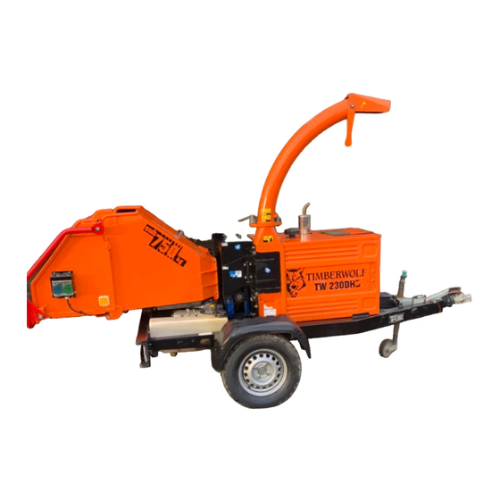
TIMBERWOLF 230DH PURPOSE OF MACHINE The Timberwolf TW75 230DH brushwood chippers are designed to chip solid wood material up to 230mm in diameter. The maximum cross-section hardwood for continuous feed is 28500 sq. mm.They are capable of chipping over 9 tonnes of brushwood per hour. -
Page 4: Parts Location Diagrams 3
PARTS LOCATOR fig 2. - Page 5 PARTS LOCATOR fig 3.
-
Page 6: Safe Working
SAFE WORKING WARNING The Chipper will feed material through on its own. To do this, it relies on sharp blades both on the feed rollers and the chipper rotor. To keep the blades sharp, only feed the machine with clean brushwood. DO NOT put muddy / dirty wood, roots, potted plants, bricks, stones or metal into the chipper. -
Page 7: General Safety Matters - Do's And Dont's
SAFE WORKING GENERAL SAFETY MATTERS D O ’ S A N D D O N T ’ S ALWAYS stop the chipper engine before making DO NOT use chipper unless available light is any adjustments, refuelling, or cleaning. sufficient to see clearly. ALWAYS check machine has stopped rotating DO NOT... -
Page 8: Noise Test
SAFE WORKING NOISE TEST MACHINE: TW75 230DH NOTES: Tested Chipping 150mm x 150mm Corsican Pine 1.5m in length Noise levels above 90dB (A) will be experienced at the working position. Wear ear protection at all times to prevent possible damage to hearing. All persons within a 4 metre radius must also wear good quality ear protection. -
Page 9: Operating Instructions
OPERATING INSTRUCTIONS SAFE TRANSPORTATION WHEN towing a chipper the maximum speed limit is 60 mph. rough or bumpy road surfaces reduce speed accordingly to protect your machine from unnecessary vibration. WHEN towing off road be aware of objects that may catch the chipper undergear. WHEN towing off road ensure inclination is not excessive. -
Page 10: Delivery
OPERATING INSTRUCTIONS DELIVERY All Timberwolf 75/230DH machines have a full pre - delivery inspection before leaving the factory and are ready to use. Read and understand this instruction manual before attempting to operate the Chipper. In particular, read pages 5-7 which contain important health and safety information and advice. -
Page 11: Auto Controls
OPERATING INSTRUCTIONS AUTO CONTROLS The no stress unit controls the feed rate of the material going into the chipping chamber. If the engine speed is below the predetermined level the No Stress Unit will not allow the feed rollers to work in either forward or reverse until the rotor speed rises above the predetermined level, at which point the feed rollers will start turning without warning. -
Page 12: Stopping The Engine
OPERATING INSTRUCTIONS STOPPING THE ENGINE PUSH the blue button to reduce the engine speed to idle. LEAVE the engine running for 1 minute. TURN the power switch to position 0. The engine should stop after a few seconds. BEFORE USING THE CHIPPER IT IS ESSENTIAL TO CARRY OUT THE FOLLOWING TESTS to check safety equipment - this sequence of tests will only take a few seconds to carry out. -
Page 13: Chipping
OPERATING INSTRUCTIONS CHIPPING Wood up to 230mm diameter can be fed into the feed funnel. Put the butt end in first and engage it with the feed roller. The hydraulic feed rollers will pull the branch into the machine quite quickly. Large diameter material will have its feed rate automatically controlled by the no stress unit. -
Page 14: Service Instructions
SERVICE INSTRUCTIONS WARNING ALWAYS IMMOBILISE THE MACHINE BY STOPPING THE ENGINE, REMOVING THE IGNITION KEY AND DISCONNECTING THE BATTERY BEFORE UNDERTAKING ANY MAINTENANCE WORK. Table 1. Service Schedule Daily Check Hours Hours Hours Year Do jobs below: Check engine oil - top up if necessary. Check for engine oil / hydraulic oil leaks. -
Page 15: Engine Maintenance
SERVICE INSTRUCTIONS ENGINE MAINTENANCE For all maintenance relating to the engine refer to the engine manufacturers handbook. It is supplied with the engine. SAFE MAINTENANCE ALWAYS IMMOBILISE THE ENGINE BEFORE UNDERTAKING ANY MAINTENANCE WORK ON THE CHIPPER BY REMOVING THE KEY AND DISCONNECTING POSITIVE LEAD AT THE BATTERY. -
Page 16: Change Blades
SERVICE INSTRUCTIONS CHANGE BLADES WARNING Wear riggers gloves for the blade changing operation. fig 9. fig 10. fig 8. THIS PROCEDURE SHOULD ONLY BE UNDERTAKEN WITH THE DISCHARGE IN PLACE. Turn off the chipper and remove the key. If the blades are to be renewed, place the blade on a flat surface and tap the top of Remove the negative battery lead. -
Page 17: Check Fittings
SERVICE INSTRUCTIONS CHECK FITTINGS The Timberwolf 75/230 is subject to large vibrations during the normal course of operation. Consequently there is always a possibility that nuts and bolts will work themselves loose. It is important that periodic checks are made to ensure the security of all fasteners. Fasteners should be tightened using a torque wrench to the settings listed below . -
Page 18: Change Hydraulic Oil And Filter
SERVICE INSTRUCTIONS CHANGE HYDRAULIC OIL AND FILTER WARNING Use plastic gloves to keep oil off skin and dispose of the used oil and filter in an ecologically sound way. The oil and filter should be changed once a year or at any time it becomes contaminated. -
Page 19: Sharpen The Roller Blades
SERVICE INSTRUCTIONS SHARPEN THE ROLLER BLADES Stop the machine and remove the ignition key. fig 17. Unbolt the control box and safety switch from the funnel. Using lifting equipment remove the feed funnel. Use an angle grinder to re create and edge. The rollers may be turned by hand to access successive edges. -
Page 20: Warranty Statement
-Performance of the required maintenance listed in your Entec instruction manual. -In the event of a failure the Entec authorised Timberwolf dealer is to be notified within 10 days of failure and the equipment is to be made available for unmolested inspection by the dealer technician. -
Page 21: Ec Declaration Of Conformity Certificate
TIMBERWOLF 230DH... -
Page 22: Identification Plates
TIMBERWOLF 230DH IDENTIFICATION PLATES ENTEC INDUSTRIES LTD CE PLATE ENTEC UK STOWMARKET, SUFFOLK IP14 5AY Date of Manuf. Serial No. Trailer Type Equip. Fitted Nominal Pwr. Gross Weight CHASSIS IDENTIFICATION PLATE... - Page 23 DANGER! KEEP HANDS AND FEET OUT READ THE INSTRUCTION MANUAL. THE INSTRUCTION MANUAL WITH THIS MACHINE CONTAINS IMPORTANT OPERATING, MAINTENANCE AND TIMBERWOLF HEALTH AND SAFETY INFORMATION. 2641 FAILURE TO FOLLOW THE INFORMATION CONTAINED IN THE INSTRUCTION MANUAL MAY LEAD TO DEATH OR SERIOUS INJURY.
-
Page 24: Stickers 22
STICKERS... -
Page 25: Wiring Diagrams
WIRING DIAGRAM... - Page 26 WIRING DIAGRAM...
- Page 27 WIRING DIAGRAM...
-
Page 28: Circuit Diagram
CIRCUIT DIAGRAM... -
Page 29: Hydraulic Layout
HYDRAULIC LAYOUT TANK FILTER HY2685 HY2687 PUMP HY2686 HY1715 HY1715 BULKHEAD HY1716 HY1718 MOTOR MOTOR HY1717... -
Page 31: Parts Lists
T T I I M M B B E E R R W W O O L L F F T T I I M M B B E E R R W W O O L L F F T T W W 7 7 5 5 / / 2 2 3 3 0 0 D D H H T T W W 7 7 5 5 / / 2 2 3 3 0 0 D D H H PARTS LISTS... -
Page 32: Chassis
CHASSIS Date Last Modified: 3rd Nov 02... -
Page 33: Rotor Housing
ROTOR HOUSING Date Last Modified: 19th Dec 03 Item Part No Part Name Q’ty Item Part No Part Name Q’ty M8 P Nyloc Nut 1692 Limit Switch M8 A Washer M4/35 Pan Pozi 2253 Hinge Pin M10/35 Bolt 2505O Rotor Housing Top Section 1 M10 A Washer M8/20 Bolt M10 T Nyloc Nut... -
Page 34: Rotor
ROTOR Date Last Modified: 23rd Oct 03... -
Page 35: Discharge
DISCHARGE Item Part No Part Name Q’ty 1521 M12/190 Bolt M12 C Washer 2234FO Discharge Bucket M12 P Nyloc Nut 2670FO Discharge Tube 1580 M10/60 Bolt 2352 Pivot Bush Washer 2236 Pivot Bush M10 T Nyloc Nut 2350S Control Link Arm 1687FS Discharge Clamp Plate 1 2239S... -
Page 36: Roller Box
ROLLER BOX Date Last Modified: 5th April 04 Item Part No Part Name Q’ty Item Part No Part Name Q’ty 2599F Link Bar 2555 Horizontal Anvil M10 A Washer 2409 M16/80 Caphead M10/25 Bolt M20/70 Caphead 1581 M12/35 Caphead 2474M Roller Box 1577 Hydraulic Motor... -
Page 37: Funnel
FUNNEL Date Last Modified: 6th April 04 Item Part No Part Name Q’ty Item Part No Part Name Q’ty 2809F Control Box (detail on next page) 1605 Stainless Spacer M8/10 Bolt 1599 Bearing Washer 1644 M8 Anti-Vibration Mount 3011F Funnel M8 C Washer See Wiring Diagram 1601... -
Page 38: Control Box
CONTROL BOX Date Last Modified: 4th Jan 04 Item Part No Part Name Q’ty Item Part No Part Name Q’ty 2794FB Control Box Cover 2807 AV Mount 20 x 16 2803 M10/240 Bolt M5 A Washer M10 A Washer M5/10 Pan Pozi M10 T Nyloc Nut M4/40 Pan Pozi 2795FB... -
Page 39: Guards
GUARDS Date Last Modified: 28th Oct 03 Item Part No Part Name Q’ty Item Part No Part Name Q’ty 2543O Engine Side Guard 2525O Non Engine Side Guard M10/16 Bolt M10 T Nyloc Nut M10 A Washer M12/40 Bolt 2542O Motor Side Guard 1644 M8 Anti-Vibration Mount... -
Page 40: Hydraulics
HYDRAULICS Date Last Modified: 2nd Sept 02 Item Part No Part Name Q’ty Part No Part Name Q’ty 1434 Return Filter Electric Valve 2530S Hydraulic Tank Top Plated 2689 Hose Bulkhead to Bottom Motor 3/8” 1 2529 Hydraulic Tank Bulkhead Fittings 2686 Hose Pump to DCV Valve 1/2 2692... -
Page 41: Drive Train
DRIVE TRAIN Date Last Modified: 14th March 03 Item Part No Part Name Q’ty Item Part No Part Name Q’ty 2596 Drive Belt 1950 SPB 2638 1/2” Stepped Key M8/30 Bolt Pump Belt 950 XPA 2610 14 Tooth Trigger 2149 Pulley 132x2 2597 Trigger Spacer... -
Page 42: Tower
TOWER Date Last Modified: 14th March 03 Item Part No Part Name Q’ty Item Part No Part Name Q’ty 2535O Visor 2537 Main Tower Rubber Grommit M6 Plain Nut M10 C Washer Steel Strip 1252 M10/50 Bolt 1680 AV Mount 2536O Relay Panel M10 A Washer... -
Page 43: Fuel Tank
FUEL TANK Date Last Modified: 20th Oct 03 Item Part No Part Name Q’ty Item Part No Part Name Q’ty 1374 Locking Tank Cap M10 T Nyloc Nut M6/10 Bolt 1063 5mm Rubber Strip M6 C Washer 2584 Fuel Tank Jubilee Clips 2644F Fuel Tank Cover 2541S... - Page 44 AIR FILTER HOUSING Date Last Modified: 8th April 03 Supplied with engine Item Part No Part Name Q’ty Item Part No Part Name Q’ty 1926 Cyclone M8/12 Bolt 1970 Jubilee Clip 85-100mm 1969S Fitting Plate 1968 Rubber Tube 1644 AV Mount M8/20 Bolt 2517O Top Guard...
-
Page 45: Engine Parts
ENGINE PARTS 10 11 12 14 15 Date Last Modified: 19th Dec 03 Item Part No Part Name Q’ty Item Part No Part Name Q’ty 2582 Engine M12 C Washer 2679F Throttle Arm M12/200 Stud 2602 M6 Spring Swivel 1910 Belt Tension Bracket 2618 Terminal Boot... -
Page 46: Engine Bay
ENGINE BAY 10 11 14 10 Date Last Modified: 29th Oct 03 Item Part No Part Name Q’ty Item Part No Part Name Q’ty 2572 Side Guard 2650 Engine Cowl Support 2671 Bonnet Catch M12/25 Bolt 5/12 Pop Rivet M12 A Washer 2672 Panel Plugs 2616... -
Page 47: Lubrication System
CONTROL PANEL Date Last Modified: 24th Oct 02 Item Part No Part Name Q’ty Item Part No Part Name Q’ty 1499 Isolator Switch 2627 Emergency Stop (OPTIONAL) 1236 M6/20 Bolt 1444 Silicon Covers M6 C Washer 1260 MTE Momentary Switch Green M6 T Nyloc Nut 1261 MTE Momentary Switch Blue... -
Page 48: Sensor Assembly
LUBRICATION SYSTEM Date Last Modified: 24th Sept 02 Item Part No Part Name Q’ty Item Part No Part Name Q’ty 2708 Y Piece 2704 Bearing Side Slide Feed 1330mm 2703 Motor Side Slide Feed 2160mm 2705 Bottom Bearing Final Feed 410mm 1 2702 Slide Final Feed 230mm 1730... -
Page 49: Stickers
SENSOR ASSEMBLY Item Part No Part Name Q’ty Rubber Grommit 2651 Remote Sensor Bracket 1904 Hose Clip 13-20mm 1759 Sensor Wabco Protector 1748F Sensor Wabco Extended Assy 1 Date Last Modified: 29th Jan 03... - Page 50 DANGER! KEEP HANDS AND FEET OUT READ THE INSTRUCTION MANUAL. THE INSTRUCTION MANUAL WITH THIS MACHINE CONTAINS IMPORTANT OPERATING, MAINTENANCE AND TIMBERWOLF HEALTH AND SAFETY INFORMATION. 2641 FAILURE TO FOLLOW THE INFORMATION CONTAINED IN THE INSTRUCTION MANUAL MAY LEAD TO DEATH OR SERIOUS INJURY.
Need help?
Do you have a question about the Entec 230DH and is the answer not in the manual?
Questions and answers