Table of Contents
Advertisement
Quick Links
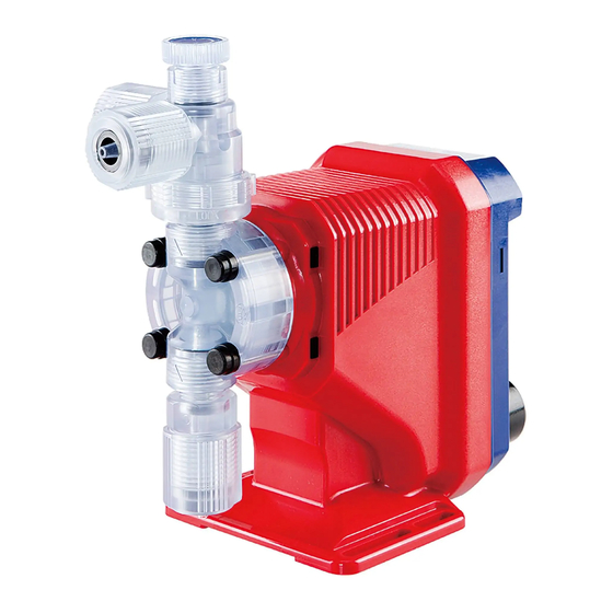
Iwaki
Electromagnetic Metering Pump
EJ-B(R) (Europe)
Instruction manual
Thank you for choosing our product.
Please read through this instruction manual before use.
This instruction manual describes important precautions and
instructions for the product. Always keep it on hand for quick
reference.
2013 IWAKI CO., LTD.
Advertisement
Table of Contents


Need help?
Do you have a question about the EJ-B Series and is the answer not in the manual?
Questions and answers