
Related Manuals for IWAKI PUMPS MDM Series


Summary of Contents for IWAKI PUMPS MDM Series
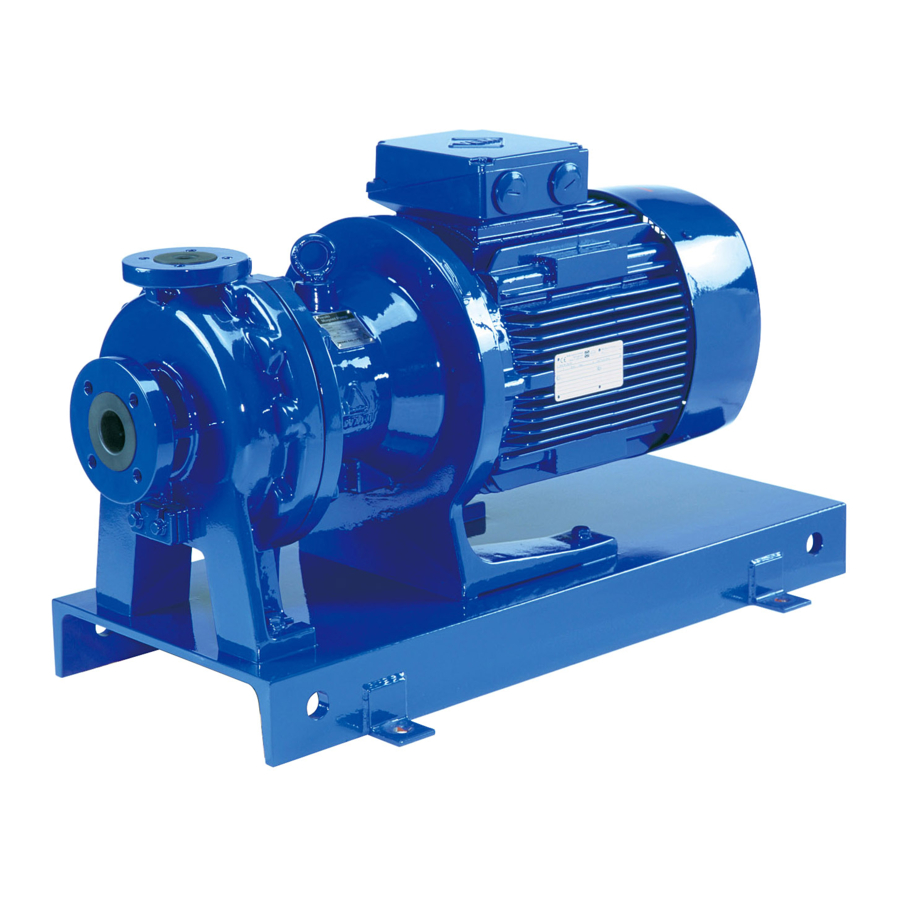
- Page 1 IWAKI Magnetic Drive Pump MDM Series (Long coupling type) Instruction Manual Read this manual before use of product This is patent pending product.
-
Page 2: Table Of Contents
Thank you for selecting IWAKI Magnetic Drive Pump MDM Series. This instruction manual, which is divided into five sections, name- ly "Safety", "Outline of Product", "Installation", "Operation" and "Maintenance", deals with the correct handling and operation procedures for the pump. To make maximum use of the pump and to ensure safe and long time operation of the pump, please read this manual thoroughly and carefully prior to operating the pump. -
Page 3: Safety Section
Safety Section For the Safe and Correct Handling of the Pump ● Before use of the pump, read carefully this "Safety Section" to prevent accidents and to avoid the damage or loss of other assets. ● Observe and abide by the instructions described in this "Safety Section". These instructions are very important for protecting pump users or other persons from hazard or from loss of assets. - Page 4 Safety Section WARNING ● Access limitation The magnet drive pump has a pair of strong magnets (the magnet capsule unit and drive magnet). The strong magnet field could adversely affect the Prohibition persons who are assisted by electronic devices such as the pacemaker. ●...
- Page 5 Safety Section CAUTION ● Do not catch the finger Magnetic force of the pump is powerful. Take care not to catch the finger in the bracket. Observe the instructions on the later pages for disassembly and assembly. ● Do not run pump dry Do not run pump dry (operation without priming water or with a suction valve closed).
-
Page 6: Outline Of Product
OUTLINE OF PRODUCT 1. Unpacking and inspection ......2. Model code ..........3. Conditions to be used ....... 4. Structure and names of parts ....- 4 -... -
Page 7: Unpacking And Inspection
1. Unpacking and inspection After unpacking of the pump, check the following points. (1) If the product is ordered one. Check model code, discharge capacity, discharge pressure, voltage which are written on nameplate of pump and motor to see if they conform to your order. -
Page 8: Model Code
2. Model code MDM 80-50-160 P KK C 075 I - D 2 H Pump sizes Suction Discharge Nominal impeller diameter × 160/200 × × Casing material P: PFA Bearing/spindle material KK: SiC/SiC Type of motor to be mounted C: Foot mounted motor type Motor output 022: 2.2 kW, 040: 4.0 kW,... -
Page 9: Conditions To Be Used
3. Conditions to be used 1. Permissible pressure Permissible pressure of the pump is 1.6 MPa. Pay attention so that the pump discharge pressure does not exceed this figure. 2. Slurry containing liquid Basically slurry containing liquid can not be handled but SiC bearing type (KK type) can handle it in the following conditions: •... -
Page 10: Structure And Names Of Parts
4. Structure and names of parts 554.5 554.6 350 901.6 903.2 940.1 908.1 159 900 901.5 858 161 400.1 942 230 100.1 122.2 901.3 554.3 500.3 400.3 314.2 554.4 901.4 314.1 122.1 321.2 901.1 554.1 500.1 554.8 901.8 400.2 321.1 314.3 314.4 Q'ty... -
Page 11: Installation
INSTALLATION 5. Installation ..........6. Piping ............7. Electrical wiring ......... 8. Protection ........... - 9 -... -
Page 12: Installation
5. Installation Example of recommended piping Discharge pipe Discharge valve Check valve Pressure gauge Motor Pump Flexible joint Vacuum gauge Suction pipe Suction valve Within Gate valve Air vent piping Pipe support 1. Installed position • Install and fix the pump on the foundation which is not affected by vibration generated by other machines. •... -
Page 13: Piping
6. Piping 1. Tightening of pipe flange Table below shows the bolt size and tightening torque for the connection of pipe flange to pump flange. Tightening torque is the figure when metallic flange and rubber gasket are used. Bolt size Tightening torque 78.4 N ⋅... - Page 14 3. Suction piping (1) Flooded suction Flooded suction is recommended. (2) Pipe diameter Pipe diameter should be larger than pump inlet bore. (3) Shortest piping Employ less bends and shortest piping length. (4) Straight piping Employ straight pipe just before pump inlet port. Pump inlet bore 50A or smaller : Straight pipe of 500 mm or longer Pump inlet bore 65A or larger : Straight pipe of 8 times as larger than inlet port For the easy pump dismantling and maintenance, install a removable short length pipe of 300mm or so in straight...
-
Page 15: Electrical Wiring
(3) Gate valve Install the gate valve in discharge piping to adjust flow rate and to protect motor from over loading. If the check valve is also installed, recommended arrangement is : Pump → Check valve → Gate valve (4) Pressure gauge Install a pressure gauge in discharge piping to check the operating conditions such as discharge head etc. -
Page 16: Operation
OPERATION 9. Precautions on operation ......10. Operation (Starting) ......... 11. Pump stopping .......... - 14 -... -
Page 17: Precautions On Operation
9. Precautions on operation CAUTION ● Never operate pump dry or with suction side valve closed. ● Do not run pump dry (operation without priming water or with a suction valve closed). Otherwise, inter- nal parts are excessively worn by friction heat and fatal pump damage results. * If the pump runs dry by mistake, turn off power and leave it for more than one hour to cool it down. -
Page 18: Operation
10. Operation (Starting) 1. Fully close discharge valve and fully open suction valve. 2. Fill liquid into pump • In case of flooded suction, confirm if suction valve is fully opened. • In case of suction lift, prime to fill liquid into suction piping. 3. -
Page 19: Maintenance
MAINTENANCE 12. Troubleshooting ........13. Maintenance & inspection ..... 14. Disassembling & assembling ....15. Repair parts list ......... - 17 -... -
Page 20: Troubleshooting
12. Troubleshooting Symptom on pump Check & countermeas- Troubles Cause When disch. valve When disch. valve ures closed opened Liquid can not Press. gauge & vac- • Lack of priming • Stop pump and replen- be sucked liquid ish pump with liquid to uum gauge indicate zero. - Page 21 Symptom on pump Check & countermeas- Troubles Cause When disch. valve When disch. valve ures closed opened Pressure gauge & vac- Pressure is high but • Too high actual • Check actual head of Discharge uum gauge indicates vacuum is normal. head or too large discharge piping and capacity is...
-
Page 22: Maintenance & Inspection
13. Maintenance & inspection Warning • Magnetic force is very strong. Pay attention when you handle the magnet capsule or driving magnet so that fingers can not be injured by attraction of magnets. • The persons who are assisted by electronic devices such as pacemakers etc. are prohibited to approach the magnet capsule and drive magnet. - Page 23 2. Wear limit of bearing and spindle (Time to be replaced) Unit: mm Spindle outer dia. Bearing inner dia. Model New one Wear limit New one Wear limit MDM50-32-160, MDM65-40-160 MDM50-32-200, MDM80-50-160 Note1. When the clearance between bearing inner dia. and spindle outer dia. exceeds 1 mm, replace by new ones.
- Page 24 4. Ball bearing The life span of ball bearing is various depending on working temperature. The continuous working temperature of outer ball of the bearing must be below 70 deg.C. If the working temperature exceeds 70 deg.C, the deterioration of grease on bearing progresses. Secure the working condition within 70 deg.C of working temperature.
-
Page 25: Disassembling & Assembling
14. Disassembling & assembling Tool list Following tools are necessary to disassemble and assemble the pump. MDM50-32-160/-200 Tool Remarks /MDM65-40-160 /MDM80-50-160 13mm Spanner /19mm 1 pc/each /24mm 4mm and 5mm Hex wrench Plastic round bar 34 mm dia. × 100 L To remove/mount the bearing 1 unit Plastic welder or industrial dryer... - Page 26 (6) Separate pump body from foot support by screwing two bolts (M12 × 90) from motor side through bolt threads holes of foot support. Screw in bolts alternatively to remove foot support backward. (Screw in bolts by approx. 75 mm). (7) Pull out backward bearing housing and bracket by lift- ing them by crane or so.
- Page 27 2. Removal of impeller and bearing (1) Stand up the claw of rear ring (314.4) after it was heated by plastic welder or industrial dryer. (2) Apply plastic made round bar of 34 mm dia. × 100L on the bearing end through impeller side and remove bear- ing (310) and rear ring (314.4) using hand press etc.
- Page 28 3. Replacement of mouth ring (1) Stand up the claw of impeller after it was heated by plas- tic welder or industrial dryer. (2) Replace the mouth ring (314.2), and fix it by heating the claw with plastic welder or industrial dryer and push the claw down.
- Page 29 6. Bearing housing dismantlement (1) Remove hex. head bolts (901.6). Be careful no to hit drive magnet unit with bracket when removing bracket. (2) Loosen hex. soch set screws (908.1) which are holding drive magnet unit. Remove the drive magnet unit from drive shaft.
- Page 30 (6) Use a puller to remove ball bearing (321.1)(321.2) from drive shaft. Be careful not to scratch the sliding surface between drive shaft and shaft seal (420). (7) Insert a flat head of screw driver between bearing hous- ing and shaft seat to remove shaft seal (420). In case bearing housing is scratched, sandpaper it.
- Page 31 7. Bearing housing assembly (1) Fit shaft seal (420) to bearing housing. Apply grease on the periphery of shaft seal and fit it with a press. In doing so, try not to scratch seal lip. (2) Fit ball bearing to drive shaft with a press. There is a dif- ference in size between front ball bearing and rear ball bearing.
- Page 32 8. Assembling Assemble the pump in reverse procedures paying attention to the following points. • Replacement of gasket Do not fail to replace the gasket by new one. Pay attention so that it cannot be forgotten to be put or it can be mounted correctly without twist or bite.
-
Page 33: Repair Parts List
15. Repair parts list - 31 -... - Page 34 Pump parts list 50-32-160 50-32-200 65-40-160 80-50-160 Parts name Material code Q'ty Remarks Code No. Code No. Code No. Code No. With drain hole 100.1+ Front casing MDM1007 MDM1013 MDM1009 MDM1011 314.1 Without drain hole MDM1006 MDM1012 MDM1008 MDM1010 122.1 Drain plate MDM0009 MDM0009 MDM0009...
- Page 35 Impeller parts list (Standard model) 50-32-160 50-32-200 65-40-160 80-50-160 Motor Impeller Parts name Q'ty Remarks power size Code No. Code No. Code No. Code No. Impeller MDM0740 MDM0741 MDM0742 MDM0743 MDM0744 MDM0745 MDM0746 MDM0669 MDM0683 MDM0654 MDM0215 MDM0379 MDM0289 MDM1033 MDM0290 MDM0747 MDM01035...
- Page 36 Impeller parts list (H-type) 50-32-200 Parts name Impeller size Motor power Q'ty Remarks Code No. 4.0/5.5/7.5kw MDM0812 For H -type 230+ Impeller/magnet capsule ass'y 314.2 4.0/5.5/7.5kw MDM0813 For H -type 4.0/5.5/7.5kw MDM0814 For H -type 4.0/5.5/7.5kw MDM0815 For H -type 4.0/5.5/7.5kw MDM0816 For H -type...
- Page 37 Impeller parts list (T-type) 50-32-160 50-32-200 65-40-160 80-50-160 Motor Impeller Parts name Q'ty Remarks power size Code No. Code No. Code No. Code No. All outputs For T -type 230+ Impeller/magnet capsule ass'y MDM0820 All outputs 314.2 For T -type MDM0821 All outputs For T -type...
-
Page 38: Ec Declaration Of Conformity
(PRODUCT) DECLARE UNDER OUR SOLE RESPONSIBILITY THAT THE PRODUCTS MAGNETIC DRIVE PUMP (MODEL NAME) MDM SERIES TO WHICH THIS DECLARATION RELATES ARE IN CONFORMITY WITH THE FOLLOWING STANDARDS OR DIRECTIVES AS FAR AS APPLICABLE (DIRECTIVES) MACHINERY DIRECTIVE 2006/42/EC (ANNEX IIA) -
Page 39: Information On Ce Conformity
Information on CE conformity ■ Information on CE conformity of pump units when the motor is fitted by the cus- tomer (dealer/operator) We hereby confirm the CE conformity of our pump unit provided that the following criteria about intended use are satisfied as described in this instruction manual: - Motor conformity in accordance with any relevant EC directives which are currently ef- fective. - Page 40 TEL: +61 2 9899 2411 FAX: +61 2 9899 2421 Germany / IWAKI Europe GmbH Sweden / IWAKI Sverige AB China (Hong Kong) / IWAKI Pumps Co., Ltd. TEL: +49 2154 9254 50 FAX: +49 2154 9254 55 TEL: +46 8 511 72900 FAX: +46 8 511 72922...
Need help?
Do you have a question about the MDM Series and is the answer not in the manual?
Questions and answers