Advertisement
Quick Links
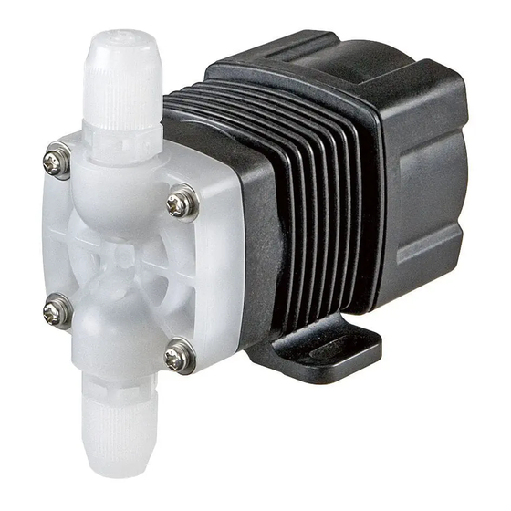
Iwaki Hi-Resolution Pump
HRP (Standard)
Instruction manual
Thank you for choosing our product.
Please read through this instruction manual before use.
This instruction manual describes important precautions and
instructions for the product. Always keep it on hand for quick
reference.
© 2009 IWAKI CO.,LTD.
Advertisement

Related Manuals for IWAKI PUMPS HRP-54V/H-1


Summary of Contents for IWAKI PUMPS HRP-54V/H-1
- Page 1 Iwaki Hi-Resolution Pump HRP (Standard) Instruction manual Thank you for choosing our product. Please read through this instruction manual before use. This instruction manual describes important precautions and instructions for the product. Always keep it on hand for quick reference. ©...
- Page 2 Open the package and check that the product conforms to your order. If any problem or inconsistency is found, immediately contact your distributor. a. Check if the delivery is correct. Check the nameplate to see if the informa- tion such as model codes, discharge capac- ity and discharge pressure are as ordered.
-
Page 3: Table Of Contents
Contents ..................... 2 Safety instructions ............... 5 WARNING ......................6 CAUTION ......................7 ..................9 Outline ..................11 .....................11 .......................13 ..................14 Installation .................. 15 ....................15 ......................16 ......................20 Operation ..................24 .................... 24... - Page 4 Maintenance ................30 ..................... 30 ......................31 .................. 33 ..............37 ....................42 ..............43 HRP-54V HRP-54H...
-
Page 5: Safety Instructions
Safety instructions Read through this section before use. This section describes important information for you to prevent personal injury or property damage. WARNING CAUTION Requirement Wear Grounding Caution Electrical Prohibited Do not rework protection shock or alter Safety instructions... -
Page 6: Warning
WARNING Electrical shock Requirement Prohibited Do not remodel Wear protectors Prohibited Prohibited WARNING... -
Page 7: Caution
CAUTION Requirement Prohibited Caution Prohibited Caution Prohibited Requirement CAUTION... - Page 8 Caution Prohibited Requirement Prohibited Requirement Caution CAUTION...
- Page 9 Caution – Requirement Caution Caution Caution Precautions for use...
- Page 10 Caution Caution Caution Requirement Caution Precautions for use...
-
Page 11: Outline
Overview Pump characteristics, features and part names are described in this section. Pump structure & Operating principle The HRP series is a diaphragm metering pump which consists of a pump head, drive unit and control unit. A diaphragm is directly driven by electromag- netic force. - Page 12 Features Operational function The HRP pump is controlled by the external signal and falls into the following types.
- Page 14 The model code represents the following information. HRP - 5 4 V - 1 P 1 - _ _ b c d e f g PVDF...
-
Page 15: Installation
Installation This section describes the installation of the pump, tubing and wiring. Read through this section before work. Select an installation location and mount the pump. - Page 16 Connect tubes to the pump and install a check valve. Tube connection...
- Page 17 Check valve mounting Install an optional check valve to the pump siphon and overfeeding.
- Page 19 AVC check valve with an air vent (Option) AVC check valve is designed for being used with the HRP and works for both (85) 270° 270°...
- Page 20 Wiring for the power source, earthing and external signal. Power & External signal cables...
- Page 21 Pink White Black Pink White Black External signal External signal...
- Page 22 Pink White Black Pink White Black 1-5VDC 4-20mADC External device External device...
- Page 23 POWER POWER TIME TIME...
-
Page 24: Operation
Operation This section describes pump operation and setting. Run the pump after pipework and wiring is completed. adjustment before starting operation. Points to be checked Before operation, check if: Screw... - Page 25 180° Degassing The gas needs to be expelled from the pump and tubing by degassing. Expect- ed performance can not be obtained with gas in the pump. Perform degassing in the following cases.
- Page 27 Operation This pump is controlled by the external signal. Read through this section for proper operation. 83.3ms 83.3ms (spm) 20 (mA)
- Page 28 (spm) 5 (V) STOP...
- Page 29 Flow rate adjustment...
- Page 30 Maintenance This section describes troubleshooting, inspection, wear part First check the following points. If the following measures do not help removing problems, contact us or your nearest dealer.
- Page 31 Perform daily and periodic inspection to keep pump performance and safety. Daily inspection Check the following points. If you notice any abnormal or dangerous condi- tions, suspend operation immediately and inspect/solve problems. When wear parts come to the life limit, replace them with new ones. Contact us or your nearest distributor for detail.
- Page 32 Periodic inspection Retighten the pump head mounting bolts every three months evenly to the fol- lowing torque in diagonal order. Screw Before a long period of stoppage (One month or more)
- Page 33 To run the pump for a long period, wear parts need to be replaced periodically. It is recommended that the following parts are always stocked for immediate replacement. Contact us or your nearest distributor for detail. Wear part list 8000...
- Page 34 Before replacement First release the pressure from the pump and discharge line. Otherwise, liquid may gush out. Pump head/Diaphragm replacement...
- Page 37 Exploded view (AVC check valve)
- Page 38 Wear part list (AVC check valve) 8000 Wear parts replacement (AVC check valve) Solution in the discharge line may be under pressure. Release the pressure from the discharge line before disconnecting plumbing or disassembly of the pump to avoid solution spray.
- Page 42 Pump head, Drive unit & Control unit Observe instructions in this manual to dismantle the pump.
- Page 43 Power Power ø3×ø6 0-720 ø4×ø6 ° °...
- Page 44 Option PVDF...
- Page 45 Outer dimensions (101) (25) 22.5 (122) (56) 22.5...
- Page 46 EC DECLARATION OF CONFORMITY KAZUNARI NISHIKUBO IS-51K-521-1...
- Page 48 TEL: +81 3 3254 2935 FAX: +81 3 3252 8892 / IWAKI Europe GmbH Norway / IWAKI Norge AS Australia / IWAKI Pumps Australia Pty Ltd. TEL: +49 2154 9254 0 FAX: +49 2154 9254 48 TEL: +47 23 38 49 00 FAX: +47 23 38 49 01...
Need help?
Do you have a question about the HRP-54V/H-1 and is the answer not in the manual?
Questions and answers