Sign In
Upload
Download
Table of Contents
Contents
Add to my manuals
Delete from my manuals
Share
URL of this page:
HTML Link:
Bookmark this page
Add
Manual will be automatically added to "My Manuals"
Print this page
×
Bookmark added
×
Added to my manuals
Manuals
Brands
IWAKI PUMPS Manuals
Water Pump
EZ Series
Instruction manual
IWAKI PUMPS EZ Series Instruction Manual
Electronic metering pump
Hide thumbs
1
2
Table Of Contents
3
4
5
6
7
8
9
10
11
12
13
14
15
16
17
18
19
20
21
22
23
24
25
26
27
28
page
of
28
Go
/
28
Contents
Table of Contents
Troubleshooting
Bookmarks
Table of Contents
Proprietary Material
Statement of Limited Warranty
Table of Contents
Introduction
Safety and Caution Notes
Principle of Operation
Model Code
Control Module
Specifications
Electrical
Operating Conditions
Capacity/Pressure Rating
Adjustment Range
Materials of Construction
Dimensions
Installation
Unpacking
Location
Supply Tubing
Discharge Tubing
Installing Injection/Backpressure Valve
Interlocking Pump
Electrical
Operation
Priming
Adjustment and Control
Calibration
STOP Function
AC Power Interruption
Auto Degassing Valve Operation
Multifunction Valve Operation
Maintenance
Diaphragm Replacement
Valve Replacement
Tubing
Exploded View & Parts Guide
Troubleshooting
Service Policy
Advertisement
Quick Links
Download this manual
IWAKI PUMPS
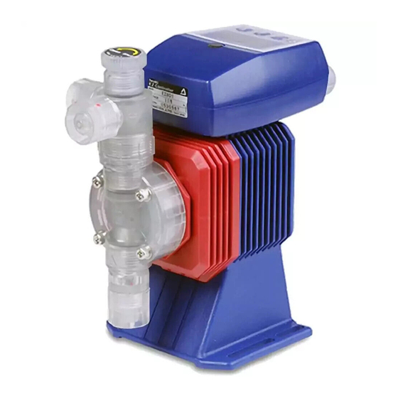
EZ Series Electronic Metering Pump
Instruction Manual
Five Boynton Road Hopping Brook Park Holliston, MA 01746 USA
TEL: 508-429-1110
WEB: www.walchem.com
Table of
Contents
Previous
Page
Next
Page
1
2
3
4
5
Advertisement
Table of Contents
Need help?
Do you have a question about the EZ Series and is the answer not in the manual?
Ask a question
Questions and answers
Related Manuals for IWAKI PUMPS EZ Series
Water Pump IWAKI PUMPS EZB11D1 Instruction Manual
Electronic metering pump (28 pages)
Water Pump IWAKI PUMPS EWN-R Instruction Manual
Electromagnetic metering pump, standard (112 pages)
Water Pump IWAKI PUMPS EWN-R Instruction Manual
(116 pages)
Water Pump IWAKI PUMPS EHN-B16 Instruction Manual
Electromagnetic metering pump (92 pages)
Water Pump IWAKI PUMPS ES-B Series Instruction Manual
Electromagnetic metering pump (24 pages)
Water Pump IWAKI PUMPS EJ-B Instruction Manual
Electromagnetic metering pump (56 pages)
Water Pump IWAKI PUMPS EJ-B Series Instruction Manual
Electromagnetic metering pump (59 pages)
Water Pump IWAKI PUMPS EJ-B16 Instruction Manual
Electromagnetic metering pump (59 pages)
Water Pump IWAKI PUMPS EH-E Series Instruction Manual
Electromagnetic metering pump (52 pages)
Water Pump IWAKI PUMPS EWN-R Series Instruction Manual
Electromagnetic metering pump (124 pages)
Water Pump IWAKI PUMPS EHN-B11VC Manual
Electromagnetic metering pump (68 pages)
Water Pump IWAKI PUMPS EWN-WCL Instruction Manual
Electromagnetic metering pump (for frc control) (100 pages)
Water Pump IWAKI PUMPS EHN-R Instruction Manual
Electromagnetic metering pump (92 pages)
Water Pump IWAKI PUMPS EH-B10 Instruction Manual
Electromagnetic metering pump (64 pages)
Water Pump IWAKI PUMPS EHN-YN Instruction Manual
Electromagnetic metering pump (84 pages)
Water Pump IWAKI PUMPS EWN Series Instruction Manual
Electromagnetic metering pump (132 pages)
This manual is also suitable for:
Ezb11d1
Ezb11d2
Ezb16d1
Ezb16d2
Ezb21d1
Ezb21d2
...
Show all
Ezb31d1
Ezb31d2
Ezc16d1
Ezc16d2
Ezc21d1
Ezc21d2
Ezc31d1
Ezc31d2
Ezc36d1
Ezc36d2
Table of Contents
Print
Rename the bookmark
Delete bookmark?
Delete from my manuals?
Login
Sign In
OR
Sign in with Facebook
Sign in with Google
Upload manual
Upload from disk
Upload from URL


Need help?
Do you have a question about the EZ Series and is the answer not in the manual?
Questions and answers