
Related Manuals for Moxa Technologies TCC-100 Series


Summary of Contents for Moxa Technologies TCC-100 Series
- Page 1 Moxa TCC-100 Series Hardware Installation Guide Twelfth Edition, January 2015 www.moxa.com/product © 2015 Moxa Inc. All rights reserved. P/N: 1802001000319 www.ipc2u.ru www.moxa.pro...
- Page 1 Moxa TCC-100 Series Hardware Installation Guide Twelfth Edition, January 2015 www.moxa.com/product © 2015 Moxa Inc. All rights reserved. P/N: 1802001000319 www.ipc2u.ru www.moxa.pro...
- Page 1 Moxa TCC-100 Series Hardware Installation Guide Twelfth Edition, January 2015 www.moxa.com/product © 2015 Moxa Inc. All rights reserved. P/N: 1802001000319...
- Page 2 Moxa TCC-100 Series Hardware Installation Guide The software described in this manual is furnished under a license agreement and may be used only in accordance with the terms of that agreement. Copyright Notice © 2015 Moxa Inc. All rights reserved.
- Page 2 Moxa TCC-100 Series Hardware Installation Guide The software described in this manual is furnished under a license agreement and may be used only in accordance with the terms of that agreement. Copyright Notice © 2015 Moxa Inc. All rights reserved.
- Page 2 Moxa TCC-100 Series Hardware Installation Guide The software described in this manual is furnished under a license agreement and may be used only in accordance with the terms of that agreement. Copyright Notice © 2015 Moxa Inc. All rights reserved.
-
Page 3: Technical Support Contact Information
Technical Support Contact Information www.moxa.com/support Moxa Americas Moxa China (Shanghai office) Toll-free: 1-888-669-2872 Tel: +86-21-5258-9955 Tel: +1-714-528-6777 Fax: +86-21-5258-5505 Fax: +1-714-528-6778 Moxa Europe Moxa Asia-Pacific Tel: +49-89-3700399-0 Tel: +886-2-8919-1230 Fax: +49-89-3700399-99 Fax: +886-2-8919-1231 Moxa India Tel: +91-80-4172-9088 Fax: +91-80-4132-1045 www.ipc2u.ru www.moxa.pro... -
Page 3: Technical Support Contact Information
Technical Support Contact Information www.moxa.com/support Moxa Americas Moxa China (Shanghai office) Toll-free: 1-888-669-2872 Tel: +86-21-5258-9955 Tel: +1-714-528-6777 Fax: +86-21-5258-5505 Fax: +1-714-528-6778 Moxa Europe Moxa Asia-Pacific Tel: +49-89-3700399-0 Tel: +886-2-8919-1230 Fax: +49-89-3700399-99 Fax: +886-2-8919-1231 Moxa India Tel: +91-80-4172-9088 Fax: +91-80-4132-1045... -
Page 4: Table Of Contents
Table of Contents 1. Introduction ............. 1 Overview ..............2 Product Features ............4 Package Checklist ............4 Product Specifications........... 4 Schematic ..............6 LED Indicators ............. 7 2. Installation ............... 8 Hardware Installation ........... 9 Termination Resistor Diagram ........13 Function Diagram ............ -
Page 5: Introduction
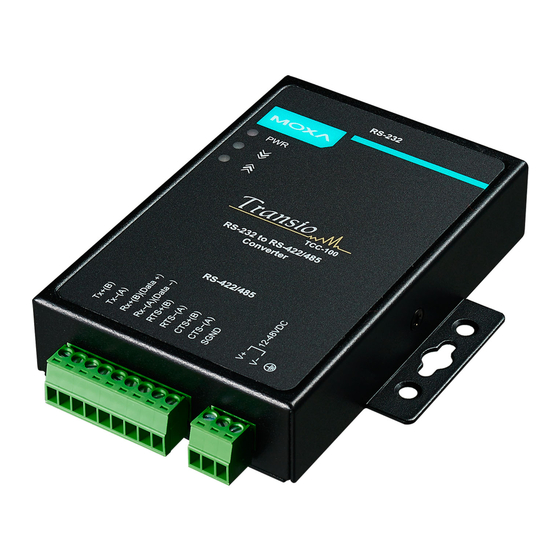
Introduction The TCC-100 series consists of RS-232 to RS-422/485 media converters. The “I” versions, the TCC-100I and TCC-100I-T come with 2 kV isolation protection. The following topics are covered in this chapter: Overview Product Features Package Checklist ... -
Page 5: Introduction
Introduction The TCC-100 series consists of RS-232 to RS-422/485 media converters. The “I” versions, the TCC-100I and TCC-100I-T come with 2 kV isolation protection. The following topics are covered in this chapter: Overview Product Features Package Checklist ... -
Page 5: Introduction
Introduction The TCC-100 series consists of RS-232 to RS-422/485 media converters. The “I” versions, the TCC-100I and TCC-100I-T come with 2 kV isolation protection. The following topics are covered in this chapter: Overview Product Features Package Checklist ... -
Page 6: Overview
DIN-rail mounting, terminal block wiring, an external terminal block power, and optical isolation for system protection, makes the TCC-100 series suitable for use in critical industrial environments. Your RS-232 devices can be used as part of an industrial RS-422/485 network, but without any hardware or software changes. -
Page 6: Overview
DIN-rail mounting, terminal block wiring, an external terminal block power, and optical isolation for system protection, makes the TCC-100 series suitable for use in critical industrial environments. Your RS-232 devices can be used as part of an industrial RS-422/485 network, but without any hardware or software changes. - Page 7 Moxa offers a better solution. The TCC-100 series’ terminator is configured with a DIP switch located on the outside of the converter’s casing.
- Page 7 Moxa offers a better solution. The TCC-100 series’ terminator is configured with a DIP switch located on the outside of the converter’s casing.
- Page 7 Moxa offers a better solution. The TCC-100 series’ terminator is configured with a DIP switch located on the outside of the converter’s casing.
-
Page 8: Product Features
Product Features • RS-232 to RS-422 conversion with RTC/CTS support • RS-232 to 2/4-wire RS-485 conversion • Detachable wall and DIN-rail mounting for easy RS-422/485 wiring • PWR, Tx, and Rx LEDs • ESD protection • 2 kV isolation (TCC-100I/TCC-100I-T) for both power and RS-422/485 signals •... -
Page 8: Product Features
Product Features • RS-232 to RS-422 conversion with RTC/CTS support • RS-232 to 2/4-wire RS-485 conversion • Detachable wall and DIN-rail mounting for easy RS-422/485 wiring • PWR, Tx, and Rx LEDs • 15 kV ESD protection • 2 kV isolation (TCC-100I/TCC-100I-T) for both power and RS-422/485 signals •... -
Page 8: Product Features
Product Features • RS-232 to RS-422 conversion with RTC/CTS support • RS-232 to 2/4-wire RS-485 conversion • Detachable wall and DIN-rail mounting for easy RS-422/485 wiring • PWR, Tx, and Rx LEDs • 15 kV ESD protection • 2 kV isolation (TCC-100I/TCC-100I-T) for both power and RS-422/485 signals •... - Page 9 Environmental Limits Operating TCC-100/TCC-100I: Temperature -20 to 60°C (-4 to 140 °F) TCC-100-T/TCC-100I-T: -40 to 85°C (-40 to 185 °F) Storage Temperature -40 to 85°C (-40 to 185°F) Humidity 5 to 95 %RH Power Requirements Input Power Voltage External Power 12-48 VDC, terminal block Reverse Power Protects against V+/V- reversal Protection...
- Page 9 Environmental Limits Operating TCC-100/TCC-100I: Temperature -20 to 60°C (-4 to 140 °F) TCC-100-T/TCC-100I-T: -40 to 85°C (-40 to 185 °F) Storage Temperature -40 to 85°C (-40 to 185°F) Humidity 5 to 95 %RH Power Requirements Input Power Voltage External Power 12-48 VDC, terminal block Reverse Power Protects against V+/V- reversal Protection...
- Page 9 Environmental Limits Operating TCC-100/TCC-100I: Temperature -20 to 60°C (-4 to 140 °F) TCC-100-T/TCC-100I-T: -40 to 85°C (-40 to 185 °F) Storage Temperature -40 to 85°C (-40 to 185°F) Humidity 5 to 95 %RH Power Requirements Input Power Voltage External Power 12-48 VDC, terminal block Reverse Power Protects against V+/V- reversal Protection...
-
Page 10: Schematic
WARNING The DC source should come from an external adaptor or 12 to 48 VDC source (not from DC mains) by using a transfer device. This unit should be installed or set up by a qualified service person. The 12 to 48 VDC power input is used for product version 2.0 and later. -
Page 10: Schematic
WARNING The DC source should come from an external adaptor or 12 to 48 VDC source (not from DC mains) by using a transfer device. This unit should be installed or set up by a qualified service person. The 12 to 48 VDC power input is used for product version 2.0 and later. -
Page 10: Schematic
WARNING The DC source should come from an external adaptor or 12 to 48 VDC source (not from DC mains) by using a transfer device. This unit should be installed or set up by a qualified service person. The 12 to 48 VDC power input is used for product version 2.0 and later. -
Page 11: Led Indicators
LED Indicators The TCC-100’s top panel contains three LED indicators, as described in the following table: LED Name LED Function Red indicates the power is on. Green indicates the TCC-100 is receiving data from the RS-232 port. Yellow indicates the TCC-100 is receiving data from the RS-422/485 port. -
Page 12: Installation
Installation This chapter includes information about how to install TCC-100 products, and shows function and block diagrams. The following topics are covered in this chapter: Hardware Installation Termination Resistor Diagram Function Diagram Isolation Block Diagram Typical Applications ... -
Page 13: Hardware Installation
Hardware Installation Installing the TCC-100 involves six straightforward steps: • STEP 1: Set the DIP switches • STEP 2: Attach the power supply STEP 3: Wire the terminal block • STEP 4: Attach the RS-232 converter • • STEP 5: Test the connection •... -
Page 13: Hardware Installation
Hardware Installation Installing the TCC-100 involves six straightforward steps: • STEP 1: Set the DIP switches • STEP 2: Attach the power supply STEP 3: Wire the terminal block • STEP 4: Attach the RS-232 converter • • STEP 5: Test the connection •... -
Page 13: Hardware Installation
Hardware Installation Installing the TCC-100 involves six straightforward steps: • STEP 1: Set the DIP switches • STEP 2: Attach the power supply STEP 3: Wire the terminal block • STEP 4: Attach the RS-232 converter • • STEP 5: Test the connection •... - Page 14 4-wire RS-485 2-wire RS-485 (terminator active) 2-wire RS-485 The DIP-2 switches are used to configure the pull high/low resistors for different applications. Pull High/Low Resistor DIP-2 SW1 DIP-2 SW2 150k 1k (default) NOTE We recommend setting the pull high/low resistor to 1k (ON/ON) when termination is enabled.
- Page 14 4-wire RS-485 2-wire RS-485 (terminator active) 2-wire RS-485 The DIP-2 switches are used to configure the pull high/low resistors for different applications. Pull High/Low Resistor DIP-2 SW1 DIP-2 SW2 150k 1k (default) NOTE We recommend setting the pull high/low resistor to 1k (ON/ON) when termination is enabled.
- Page 14 4-wire RS-485 2-wire RS-485 (terminator active) 2-wire RS-485 The DIP-2 switches are used to configure the pull high/low resistors for different applications. Pull High/Low Resistor DIP-2 SW1 DIP-2 SW2 150k 1k (default) NOTE We recommend setting the pull high/low resistor to 1k (ON/ON) when termination is enabled.
- Page 15 PWR LED located on the TCC’s top panel should turn red. NOTE The TCC-100 series supports reverse power protection. That is, it will automatically detect which power wire is negative, and which is positive.
- Page 15 PWR LED located on the TCC’s top panel should turn red. NOTE The TCC-100 series supports reverse power protection. That is, it will automatically detect which power wire is negative, and which is positive.
- Page 15 PWR LED located on the TCC’s top panel should turn red. NOTE The TCC-100 series supports reverse power protection. That is, it will automatically detect which power wire is negative, and which is positive.
- Page 16 RS-422 When using the RS-422 wiring option, first follow the 4-wire RS-485 wiring instructions given above. Optional RTS/CTS Handshaking Signals If your software is set up to send and receive RTS/CTS signals over separate wires, you should also connect from RTS+(B) to CTS+, from RTS-(A) to CTS-, from CTS+(B) to RTS+, and from CTS-(A) to RTS-.
- Page 16 RS-422 When using the RS-422 wiring option, first follow the 4-wire RS-485 wiring instructions given above. Optional RTS/CTS Handshaking Signals If your software is set up to send and receive RTS/CTS signals over separate wires, you should also connect from RTS+(B) to CTS+, from RTS-(A) to CTS-, from CTS+(B) to RTS+, and from CTS-(A) to RTS-.
- Page 16 RS-422 When using the RS-422 wiring option, first follow the 4-wire RS-485 wiring instructions given above. Optional RTS/CTS Handshaking Signals If your software is set up to send and receive RTS/CTS signals over separate wires, you should also connect from RTS+(B) to CTS+, from RTS-(A) to CTS-, from CTS+(B) to RTS+, and from CTS-(A) to RTS-.
-
Page 17: Termination Resistor Diagram
STEP 6: Placement Options In addition to placing the TCC-100 on a desktop or other horizontal surface, you may also use the DIN-rail or wall mount options, as illustrated below. DIN Rail Wall Mounting Termination Resistor Diagram Termination is designed to mitigate noise from the RS-422/485 transmission signals. -
Page 18: Function Diagram
Function Diagram Isolation Block Diagram www.ipc2u.ru www.moxa.pro... -
Page 18: Function Diagram
Function Diagram Isolation Block Diagram www.ipc2u.ru www.moxa.pro... -
Page 18: Function Diagram
Function Diagram Isolation Block Diagram... -
Page 19: Typical Applications
Typical Applications RS-485 Application A typical RS-485 application for the TCC-100 series is shown in the following figure. In this scenario, two TCC-100 units are used to connect two PCs to an RS-485 network. The third TCC-100 is used to connect the PLC, which is designed for the RS-232 interface, to the RS-485 network. -
Page 19: Typical Applications
Typical Applications RS-485 Application A typical RS-485 application for the TCC-100 series is shown in the following figure. In this scenario, two TCC-100 units are used to connect two PCs to an RS-485 network. The third TCC-100 is used to connect the PLC, which is designed for the RS-232 interface, to the RS-485 network.
Need help?
Do you have a question about the TCC-100 Series and is the answer not in the manual?
Questions and answers