Moxa Technologies AWK-3252A Series Quick Installation Manual
Hide thumbs
Also See for AWK-3252A Series:
- Quick installation manual (26 pages) ,
- User manual (161 pages)

Related Manuals for Moxa Technologies AWK-3252A Series


Summary of Contents for Moxa Technologies AWK-3252A Series
- Page 1 AWK-3252A Series Quick Installation Guide Moxa AirWorks Version 1.0, December 2021 Technical Support Contact Information www.moxa.com/support 2021 Moxa Inc. All rights reserved. P/N: 1802032520010 *1802032520010*...
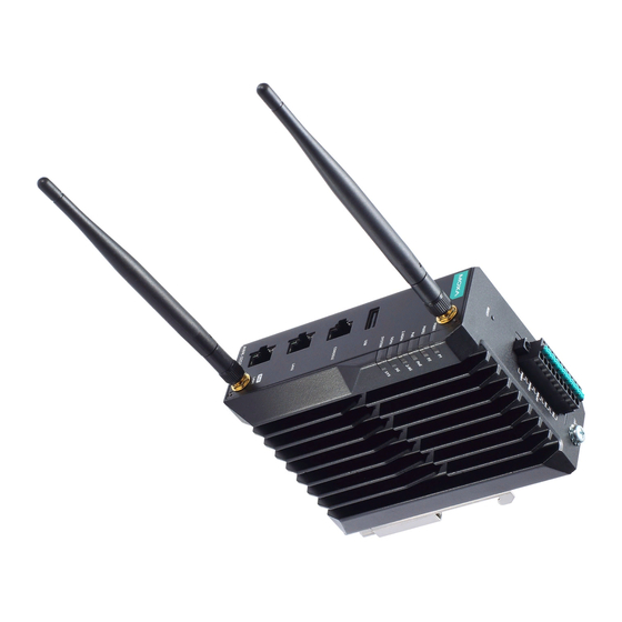
- Page 2 Overview The AWK-3252A Series is an industrial-grade AP/bridge/client with IEEE 802.11ac Wave 2 technology. This Series features concurrent dual-band Wi-Fi data transmissions up to 400 Mbps (2.4 GHz mode) and 867 Mbps (5 GHz mode) simultaneously, meeting the speed and flexibility requirements for industrial applications.
- Page 3 Panel Layout of the AWK-3252A 1. Grounding screw (M5) 11. Screw holes for wall-mounting 2. Terminal blocks for PWR1, PWR2, relay, DI 1 and DI 2 12. DIN-rail mounting kit 3. Reset button 13. Cable holder screw 4. Antenna connector A 5.
-
Page 4: Mounting Dimensions
Mounting Dimensions DIN-Rail Mounting When shipped, the metal DIN-rail mounting kit is fixed to the back panel of the AWK-3252A. Mount the AWK-3252A on to a corrosion-free mounting rail that adheres to the EN 60715 standard. STEP 1: STEP 2: Insert the upper lip of the DIN-rail Press the AWK-3252A towards the kit into the mounting rail. -
Page 5: Wall Mounting (Optional)
To remove the AWK-3252A from the DIN rail, do the following: STEP 1: Pull down the latch on the DIN- rail kit with a screwdriver. STEP 2 & 3: Slightly pull the AWK-3252A forward and lift it up to remove it from the mounting rail. -
Page 6: Wiring Requirements
STEP 3: Once the screws are fixed into the wall, insert the four screw heads through the large opening of the keyhole-shaped apertures, and then slide the AWK-3252A downwards, as indicated to the right. Tighten the three screws for added stability. WARNING •... - Page 7 • You can use the type of signal transmitted through a wire to determine which wires should be kept separate. The rule of thumb is that wiring that shares similar electrical characteristics can be bundled together. • Keep input wiring and output wiring separated. •...
-
Page 8: Terminal Block Pin Assignment
Arrester Accessories • SA-NMNF-02: Surge arrester, N-type (male) to N-type (female) • SA-NFNF-02: Surge arrester, N-type (female) to N-type (female) Terminal Block Pin Assignment The AWK-3252A comes with a 10-pin terminal block located on the top panel of the device. The terminal block contains dual power inputs, a relay output, and dual digital inputs. -
Page 9: Wiring The Relay Contact
STEP 1: Insert the negative/positive DC wires into the +/- terminals. STEP 2: Insert the plastic terminal block connector prongs into the terminal block receptor, which is located on the AWK-3252A’s top panel. NOTE Input Terminal Block (CN1) is suitable for wire size range of 16- 28 AWG (1.318-0.0804 mm²). -
Page 10: Communication Connections
STEP 1: Screw the cable holder onto the bottom of the AWK-3252A. STEP 2: After mounting the AWK-3252A and plugging in the LAN cable, tighten the cable along the device and wall. Communication Connections 10/100/1000BaseT(X) Ethernet Port Connection The 10/100/1000BaseT(X) ports located on the AWK-3252A’s front panel are used to connect to Ethernet-enabled devices. -
Page 11: Led Indicators
Description LED Indicators The front panel of the AWK-3252A contains several LED indicators. The function of each LED is described in the table below: Color State Description Front Panel LED Indicators (System) Power is being supplied from power input 1. Green PWR1 Power is not being supplied... -
Page 12: Specifications
Data is being transmitted Blinking over the 5 GHz band. Established a Wi-Fi connection to an AP/Master with a SNR value of less than Amber Data is being transmitted Blinking over the 5 GHz band. LAN LED Indicators (RJ45 Port) Color State Description... - Page 13 ATTENTION The AWK-3252A is NOT a portable mobile device and should be located at least 20 cm away from the human body. The AWK-3252A is NOT designed for the general public. To ensure that your AWK-3252A wireless network is safe and configured correctly, consult a well-trained technician to assist with the installation process.
- Page 14 APPENDIX Federal Communication Commission Interference Statement This equipment has been tested and found to comply with the limits for a Class B digital device, pursuant to Part 15 of the FCC Rules. These limits are designed to provide reasonable protection against harmful interference in a residential installation.
- Page 15 types listed below with the maximum permissible gain and required antenna impedance for each antenna type indicated. Antenna types not included in this list, having a gain greater than the maximum gain indicated for that type, are strictly prohibited for use with this device. Professional installation This is a specific product that requires professional installation and configuration, must be performed by trained technical engineers to install the antenna, please contact Moxa for further information.
- Page 16 Canada, Innovation, Science and Economic Development Canada (ISED) Notices CAN ICES-003 (A)/NMB-003(A) This device contains licence-exempt transmitter(s)/receiver(s) that comply with Innovation, Science and Economic Development Canada’s licence-exempt RSS(s). Operation is subject to the following two conditions: This device may not cause interference. This device must accept any interference, including interference that may cause undesired operation of the device.
- Page 17 type, sont strictement interdits pour une utilisation avec cet appareil. Caution: i.) the device for operation in the band 5150–5250 MHz is only for indoor use to reduce the potential for harmful interference to co-channel mobile satellite systems; Mise en garde: i.) le dispositif destiné...
Need help?
Do you have a question about the AWK-3252A Series and is the answer not in the manual?
Questions and answers