Sign In
Upload
Manuals
Brands
Aetechron Manuals
Amplifier
7224
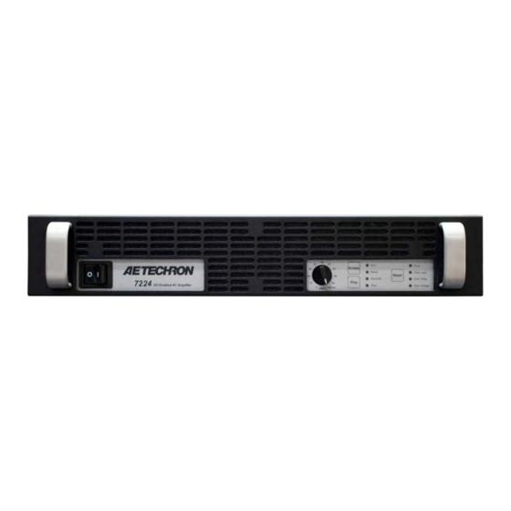
Aetechron 7224 Manuals
Manuals and User Guides for Aetechron 7224. We have
2
Aetechron 7224 manuals available for free PDF download: Operator's Manual
Aetechron 7224 Operator's Manual (71 pages)
Single-Channel Industrial Amplifiers
Brand:
Aetechron
| Category:
Amplifier
| Size: 29 MB
Table of Contents
Table of Contents
5
1 Introduction
7
Features
7
Figure 1.1 - 7224 Front Panel
7
2 Amplifier Unpacking and Installation
8
Safety First
8
Unpacking
8
Installation
8
3 Connections and Startup
9
Other Operation Modes and Configurations
9
Connecting the Load
9
Figure 3.1 - 7224 Back Panel
9
Connecting the Input Signal
10
Figure 3.2 - Closeup of the Output Terminal Resistor
10
Figure 3.3 - Connecting the Load
10
Figure 3.4 - Closeup of SIM Card
10
Connecting the AC Supply
11
Start-Up Procedure
11
Figure 3.5 - Wiring for Unbalanced or Balanced Input Connector
11
Figure 3.6 - Closeup of AC Mains Outlet
11
Figure 3.7 - Sample of Configurations Setting Label
11
4 Amplifier Operation
12
Front-Panel Controls
12
Figure 4.1 - Power Switch
12
Figure 4.2 - Gain Control
12
Figure 4.3 - Push Buttons
13
Figure 4.5 - Main Status Indicators
13
Back-Panel Controls and Connectors
15
Figure 4.7 - Back Panel Controls and Connectors
15
5 Advanced Configuration
16
Configuration Settings Located on the Main Board
16
Configuration Settings Located on the Power Supply Board
19
6 Applications
21
Remote Status and Control Using the SIM Interlock I/O Connector
21
Figure 6.1 - Remote Status and Control Pinouts
21
Figure 6.2 - Remote Run/Standby Monitor
21
Figure 6.3 - Remote Status and Reset Schematic
22
Figure 6.5 - Remote Current Monitoring
24
Figure 6.6 - Remote Current Monitoring, Alternate Method
24
Controlled Current Operation
25
Figure 6.7 - Input to Output Comparison, Controlled-Voltage Operation
25
Figure 6.8 - Input to Output Comparison, Controlled-Current Operation
25
Figure 6.9 - Factory-Installed Default RC Network
26
Figure 6.10 - Custom Compensation Location
28
Figure 6.11 - Compensation Effects on Waveform
28
Figure 6.12 - Square Wave Showing a Decrease in R Is Required
28
Figure 6.13 - Square Wave Showing an Increase in R Is Required
28
Figure 6.14 - Square Wave Showing a Decrease in C Is Required
28
Multi-Amplifier Systems
29
7 Amplifier Signal Flow
58
Input Signals
58
AC Mains Power
58
Figure 7.1 - Board-Level Functional Block Diagram
58
8 Maintenance
59
Clean Amplifier Filter and Grills
59
9 Troubleshooting
60
Introduction & Precautions
60
Visual Inspection
60
Figure 9.1 - +VCC and -VCC Point Locations
60
No Signal
61
No Leds Illuminated or no Fans
61
Overvoltage LED Lit
61
Standby LED Remains Illuminated
61
Figure 9.2 - Fuse F1 Location
61
Figure 9.3 - Interlock I/O Connector
61
Amplifier Overheats (over Temp Fault Condition)
62
Fault LED Is Illuminated
62
Factory Service
62
Advertisement
Aetechron 7224 Operator's Manual (88 pages)
Brand:
Aetechron
| Category:
Amplifier
| Size: 4 MB
Table of Contents
Table of Contents
4
Introduction
5
Features
5
Configuration Options
5
How to Use this Manual
6
Determine Your Amplifier Version
6
Safety First
7
Amplifier Unpacking and Installation
8
Unpacking
8
Installation
8
Connections and Startup
9
Other Operation Modes and Configurations
9
Connecting the Load
9
Connecting the Input Signal
10
Other Back Panel Controls and Connectors
11
Connecting the AC Supply
11
Start-Up Procedure
11
Amplifier Operation
12
Front-Panel Controls
12
Front-Panel Indicators
13
Back-Panel Controls and Connectors
16
Advanced Configuration
17
DIP Switch Configurations
17
Internal Configurations
19
Applications
25
Remote Status and Control Using the Interconnect Ports (Version D Only)
25
Remote Status and Control Using the SIM Interlock I/O Connector (All Versions)
27
Controlled Current Operation
32
Multi-Amp Systems for Increased Voltage or Current
37
Maintenance
50
Clean Amplifier Filter and Grills
50
Troubleshooting
51
Introduction & Precautions
51
Visual Inspection
51
No Signal
51
No Leds Illuminated
51
Overvoltage LED Lit
51
Standby and Stop Leds Remain Illuminated
52
Standby LED Remains Illuminated
52
Amplifier Overheats (over Temp Fault Condition)
52
Fault LED Is Illuminated
52
Factory Service
53
Configuration Settings Located on the Main Board
57
Accessing the Main Board through the Access Panel
57
Accessing the Main Board through the Top Cover
58
Advertisement
Related Products
Aetechron 7548
Aetechron 7794
Aetechron 7796
Aetechron 7228
Aetechron 7114
Aetechron 7548RLY
Aetechron 7796RLY
Aetechron 7212
Aetechron 7234
Aetechron 7220 Series
Aetechron Categories
Amplifier
Transformer
Inverter
Test Equipment
Relays
More Aetechron Manuals
Login
Sign In
OR
Sign in with Facebook
Sign in with Google
Upload manual
Upload from disk
Upload from URL