Table of Contents
Advertisement
Available languages
Available languages
Quick Links
Advertisement
Table of Contents

Subscribe to Our Youtube Channel
Related Manuals for Sensitron SMART S-IS


Summary of Contents for Sensitron SMART S-IS
- Page 1 Manuale d’istruzione / Instruction Manual SMART S-IS Rilevatore ATEX linea premium per gas tossici a sicurezza intrinseca Premium line intrinsically safe ATEX detector for toxic gas MTEX4985 R0 10/06/2021 ©2021 SENSITRON S.R.L. - All rights reserved - www. sensitron.it...
- Page 2 RELY ON THIS PRODUCT FOR THEIR SAFETY COULD SUFFER SEVERE PERSO- NAL INJURY OR DEATH. The warranties made by Sensitron s.r.l. with respect to this product are voi- ded if the product is not installed, used and serviced in accordance with the instructions in this user guide.
-
Page 3: Table Of Contents
SOMMARIO Introduzione ....................1 Descrizione generale ......................1 Identificazione rilevatore ....................2 Caratteristiche tecniche ....................2 Certificazioni ....................3 Marcatura ..........................3 Predisposizione del sito di installazione ..........5 Idoneità dei rivelatori in relazione al luogo di installazione .......5 Consigli generali ........................6 Ambiente di utilizzo ......................6 Condizioni speciali per utilizzo sicuro ........... - Page 4 SUMMARY Introduction ..................... 19 General description ......................19 Gas detector identification ....................20 Technical specifications .....................20 Certifications ....................21 Marking ...........................21 Installation site prearrangement ............. 23 Suitability of detectors in relation to the area of installation ......23 General precautions ......................23 Environment conditions ....................24 Special conditions for safe use ..............
-
Page 5: Introduzione
I rilevatori SMART S-IS sono a sicurezza intrinseca certificati ATEX e IECEx e internamente provvisti di barriera Zener e circuito di separazione galvanica. Gli SMART S-IS vengono impiegati per rilevare la presenza di gas tossici in ppm con la cella elettrochimica. La cella elettrochimica, estremamente precisa e affidabile, ha ottime presta- zioni nella rilevazione di gas a basse concentrazioni, per questo trova facile applicazione in ambienti in cui sono presenti gas tossici. -
Page 6: Identificazione Rilevatore
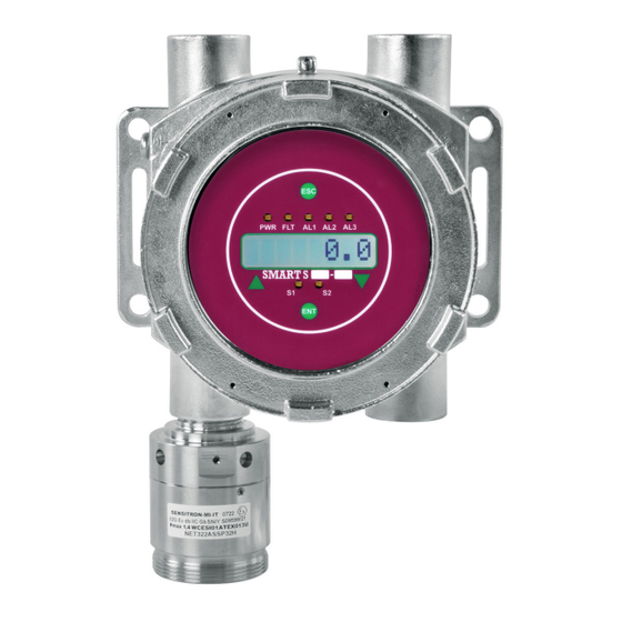
ITALIANO 1.2 Identificazione rilevatore Il codice del rilevatore SMART S-IS viene composto da quattro parti che identificano le varie parti (vedere la scheda tecnica del prodotto per ulteriori dettagli): Codice contenitore Codice trasmettitore Codice testa sensore SIS: Modello SIS rilevatore a sicurezza intrinseca. -
Page 7: Certificazioni
Norme EMC EN 50270:2015 Certificazioni I rilevatori di gas serie SMART S-IS soddisfano i requisi- ti essenziali di sicurezza e salute in accordo alla Direttiva ATEX 2014/34/UE e lo schema di certificazione IECEx. Sono strumenti costruiti per impiego in atmosfere poten-... - Page 8 ITALIANO Tabella 2) Dati riportati nella marcatura presente in targa. Variano in base alla certificazione. Sensitron S.r.l. Nome e indirizzo del fabbricante del dispositivo elettrico Viale della Repubblica 48, 20010 Cornaredo MI Italia Marcatura di conformità alle direttive europee applicabili ST/../EL/..
-
Page 9: Predisposizione Del Sito Di Installazione
ITALIANO T85 °C Massima temperatura superficiale di riferimento per pol- veri combustibili IP65 Grado di protezione IP secondo la EN /IEC 60529 (1a cifra per la protezione contro corpi solidi, 2a cifra per la pro- tezione contro liquidi) garantita quando il dispositivo di protezione contro le polveri viene utilizzato. -
Page 10: Consigli Generali
ITALIANO 3.2 Consigli generali Durante le operazioni di montaggio e installazione, gli impianti devono essere messi in si- curezza. Ricordiamo anche come in fase di installazione sia opportuno tenere in considera- zione alcune norme generali in quanto un posizionamento non corretto può pregiudicare il funzionamento ottimale del rivelatore. -
Page 11: Condizioni Speciali Per Utilizzo Sicuro
Condizioni speciali per utilizzo sicuro ³ L’installazione, l’utilizzo, la manutenzione e la riparazione dell’apparecchiatura devono essere effettuate in accodo alle presenti Istruzioni di sicurezza fornite dalla Sensitron. ³ L’installazione del rilevatore di gas deve garantire la connessione equipotenziale della custodia. -
Page 12: Collegamento A Terra
ITALIANO 5.2 Collegamento a terra La custodia deve essere collegata a terra mediante l’apposito morsetto esterno con rondella di bloccaggio antiallentamento e dispositivo meccanico antirotazione. Il collegamento esterno della messa a terra deve essere eseguito con un conduttore di sezio- ne minima pari almeno a 4 mm2. -
Page 13: Configurazione Del Rivelatore
ITALIANO JP5 : Connettore per tastierino di calibrazione JPS3 : Selezione per l’attivazione del relè K3: S1 : Spostare S1 verso il lato H per il normale Pin 1-2 chiusi: selezionato su ALLARME 2 funzionamento con il modulo HART Pin 2-3 chiusi: selezionato su ALLARME 3 (Default) S1 : Spostare S1 verso il lato K per abilitare l’uso del tastierino di calibrazione JPS2 :... -
Page 14: Collegamento Uscita Seriale Rs485
È sempre preferibile eseguire giunzioni sal- date. ³ I rilevatori SMART S-IS possono essere collegati a centrali di rivelazione gas di altre marche, purché in grado di leggere un segnale 4-20mA. ³ Si raccomanda di accertarsi che le centrali siano certificate in conformità alle norme EN /IEC 60079-29-1:2016. -
Page 15: Collegamento Con Scheda Relè (Opzionale)
5.8 Collegamento con scheda relè (opzionale) In fase di configurazione della versione display del rilevatore SMART S-IS è possibile associa- re le soglie di allarme 1, 2, 3 ed il guasto alla scheda 3 relè. Il relè 1 è associato alla condizione di guasto e Watch-Dog, mentre gli altri due si possono associare a due soglie di allarme. -
Page 16: Collaudo E Uso
ITALIANO Collaudo e uso 6.1 Accensione Al momento in cui il rivelatore viene alimentato, si accende ad intermittenza lenta il LED rosso sulla scheda base. L’uscita in corrente è 2 mA circa. Trascorsi 2 minuti e terminata la fase di warm-up, l’uscita in corrente passa a 4,0 mA. Terminata la fase di preriscaldamento il rivelatore è... -
Page 17: Manutenzione
ITALIANO Manutenzione Le verifiche e la manutenzione dei rivelatori in versione antideflagrante devono essere effet- tuate da personale esperto secondo i criteri della norma EN /IEC 60079-17. 7.1 Manutenzione preventiva Nei paesi della Comunità Europea, le prove di funzionamento in gas e le procedure di ta- ratura dei rivelatori di gas sono richieste dalle normative in vigore e definiti dalla EN /IEC 60079-29-2. -
Page 18: Sostituzione Della Testa Sensore
7.4 Sostituzione della testa sensore Qualora ci fosse la necessità, la testa sensore può essere sostituita, previa autorizzazione dalla Sensitron, con un apposito kit ed istruzioni forniti dalla Sensitron. ATTENZIONE! E’ severamente vietato e pericoloso aprire e chiudere il dispositivo in zona pericolosa con tensione inserita;... - Page 19 Errore testa Testa del sensore non adatta Selezionare e montare una testa del sen- non valida al rilevatore. sore adatta. Contattare Sensitron per mag- giori informazioni. Errore testa Testa del sensore non confi- Montare una testa del sensore configurata non configu- gurata adeguatamente adeguatamente.
-
Page 20: Riparazioni
Per garantire la protezione agli urti si consiglia di imballare lo strumento nell'imballo origi- nale o proteggerlo con fogli di film a bolle (pallinato). 10. Accessori Tabella 6) Elenco degli accessori acquistabili separatamente. Si prega di contattare Sensitron per ulteriori dettagli. Codice prodotto Descrizione... -
Page 21: Tagliando Di Garanzia Per La Riparazione
è vincolata e limitata ai termini di garanzia dichiarati dalla casa co- struttrice. Sensitron ha una politica di continuo sviluppo e miglioramento dei suoi prodotti. Pertanto, le specifiche del dispositivo descritte in questo documento possono essere modificate senza preavviso. In caso di modifica del prodotto, Sensitron declina ogni responsabilità. - Page 22 ENGLISH Pag. 18...
-
Page 23: Introduction
Zener barrier and galvanic separation circuit. SMART S-IS detectors are used to detect the presence of toxic gases in ppm by means of an electrochemical cell. The electrochemical cell is extremely reliable and it has the best performances in detection of gases at low concentration. -
Page 24: Gas Detector Identification
ENGLISH 1.2 Gas detector identification The SMART S-IS detector code consists of four parts that identify the various parts (see prod- uct data sheet for further details): Enclosure code Transmitter code Sensor head code SIS: Intrinsically safe detector, SIS model. -
Page 25: Certifications
The sensor head must be mounted downward EMC Reference standard EN50270:2015 Certifications SMART S-IS series gas detectors meet the essential health and safety requirements in accordance with the ATEX Di- rective 2014/34/EU and the international IECEx scheme. The detectors have been designed for use in potentially... - Page 26 ENGLISH Table 2) The data present on the marking label is explained below Sensitron S.r.l. Viale della Re- Name and address of the manufacturer of the electrical pubblica 48, 20010 Cornaredo device MI Italia Conformity marking for the applicable European direc- tives ST/../EL/..
-
Page 27: Installation Site Prearrangement
ENGLISH IIIC Combustible dust group T85 °C Maximum surface temperature relating to combustible dust IP65 IP degree of protection (1st number: protection against solids, 2nd number: protection against liquids) guaran- teed when the optional dust cover is applied Gb/Db EPL, Equipment Protection Level Gb or Db suitable for zone 1,2,21 and 22 surface installation -20 °C ≤... -
Page 28: General Precautions
ENGLISH 3.2 General precautions At the mounting and installation phase, be sure all safety precautions have been considered. Always remember how important the correct positioning of gas detectors is to get the op- timum response. Be careful: ³ Never to install gas detectors close to air intakes or fans causing strong air currents. ³... -
Page 29: Special Conditions For Safe Use
ENGLISH Special conditions for safe use ³ The installation, use, maintenance and restoration must be done following these Safe- ty Instructions supplied by Sensitron. ³ The gas detector installation must guarantee the equipotential connection of the en- closure. ³ Only the models equipped with dust filter can be installed in zone 21 and 22. -
Page 30: Earth Ground Connection
ENGLISH 5.2 Earth ground connection The enclosure can be connected to the earth ground through the external clamp with an- ti-loosening locking washer and anti-rotation mechanical device. To allow external earth ground connection, use a conductor with a minimum section of 4 mm2. -
Page 31: Detector Configuration
ENGLISH JP5 : Connector for calibration keypad JPS3 : Selection of activation event for Relay K3: S1 : SET S1 TOWARD H SIDE FOR NORMAL WORKING Closed on Pin 1-2 : ALARM 2 Selected WITH HART CONNECTION. Closed on Pin 2-3 : ALARM 3 Selected (Default) S1 : SET S1 TOWARD K SIDE FOR CALIBRATION WITH KEYPAD. -
Page 32: Rs485 Serial Output Connection
5.7 RS485 serial output connection To connect SMART S-IS gas detectors to RS485 bus lines, it is necessary to use a 4-wire cable, 1 pair for the RS485 bus and 1 for the power supply. It is also necessary that: ³... -
Page 33: Connection To Relay Board (Optional)
12 Vdc. 5.8 Connection to relay board (optional) During configuration of SMART S-IS detector it’s possible to associate alarm thresholds and fault signal to the relay board. Relay 1 is associated to Fault and Watch-dog. The remaining two are to be associated to two outputs of the three pre-set alarm thresholds. -
Page 34: Testing And Use
ENGLISH Testing and use 6.1 Power on When the detector is powered on the output current is nearly 2.0 mA. After 2 minutes, when the warm-up time has finished, the output current is 4.0 mA. Once the warm-up phase is over, the detector can work correctly, although the optimal per- formances will be achieved after two hours. -
Page 35: Maintenance
ENGLISH Maintenance The periodical check-ups and maintenance of the detectors, in the explosion-proof version, must be carried out by expert personnel according to the criteria of the EN /IEC 60079-17 standard. 7.1 Preventive maintenance routines Within the European Union countries, bump testing and calibration procedures of gas de- tectors are required by strict regulations and detailed in the EN /IEC 60079-29-2. -
Page 36: Sensor Head Substitution
7.4 Sensor head substitution If necessary, the sensor head can be substituted. First of all, the user must request to Sensi- tron and Sensitron will give a proper kit and instructions. WARNING! It’s strictly forbidden open and close the equipment when it’s installed in hazardous area and it’s powered-on. - Page 37 Not config- The sensor head is not con- Connect a sensor head correctly configurat- ured head figured as suggested ed. Contact Sensitron for further informa- error tion. Association The sensor head is not mem- Associate the sensor head. head error...
-
Page 38: Repair
To grant a stout protection against impacts we recommend using the original package or protect the device with bubble wrap sheets. 10. Accessories Table 6) Table of available accessories that can be purchased separately. Please contact Sensitron for further information. Part number Description STGD/AD3... -
Page 39: Warranty Coupon For Repair
In case of modification of the prod- uct, Sensitron disclaims all liability. Data may change, as well as legislation and you are strongly advised to ob- tain copies of the most recently issued regulations, standards and guidelines. This publication is not intended to form the basis of a contract. - Page 40 LEADER IN SIL2 (SIL3) FIXED GAS DETECTION SYSTEMS Contact details: SENSITRON s.r.l. Viale della Repubblica, 48 - 20007 - Cornaredo (MI) Italy TEL. +39 0293548155 - FAX +39 0293548089 - www.sensitron.it - E-mail: sales@sensitron.it...
Need help?
Do you have a question about the SMART S-IS and is the answer not in the manual?
Questions and answers