
Related Manuals for LINET LATERA


Summary of Contents for LINET LATERA
- Page 1 Instructions for Use and Technical Description LATERA Universal hospital bed D9U001L20-0101 Version: 04 Publication Date: 2022-10...
- Page 2 Service department: service@linetgroup.com Latera Universal hospital bed Author: L I N E T, s.r.o. Related links: www.linet.com D9U001L20-0101 Version: 04 Publication date: 2022-10 Copyright © L I N E T, s.r.o., 2022 Translation © L I N E T, 2022 All rights reserved.
-
Page 3: Table Of Contents
21 Standards and Regulations ........54 9.1.2 Removing the Isolating Foil ........24 9.1.3 Isolating Foil .............24 9.2 Head Board and Foot Board ........25 9.2.1 Latera Thema Head Board and Foot Board ..... 26 9.3 Potential Equalisation ..........27 9.4 Before Use ..............27 9.5 Transport ..............28 9.6 Firmware ..............28... -
Page 4: Symbols And Definitions
1 Symbols and Definitions 1.1 Warning Notices 1.1.1 Types of Warning Notices Warning notices are differentiated by the type of danger using the following key words: ► CAUTION warns about the risk of material damage. ► WARNING warns about the risk of physical injury. ► DANGER warns about the risk of fatal injury. 1.1.2 Structure of Warning Notices SIGNAL WORDS! Type and source of danger! ►... -
Page 5: Symbols On The Package
1.4 Symbols on the Package FRAGILE, HANDLE WITH CARE THIS WAY UP KEEP DRY (PROTECT FROM HUMIDITY) PAPER RECYCLING SYMBOL DO NOT USE HAND TRUCK HERE DO NOT STACK DURING STORAGE D9U001L20-0101_04... -
Page 6: Symbols And Labels On The Bed
1.5 Symbols and Labels on the Bed READ INSTRUCTIONS FOR USE. ATTENTION - CONSULT ACCOMPANYING DOCUMENTS. THERMAL PROTECTION OF TRANSFORMER ONLY SUITABLE FOR INDOOR USE PROTECTION AGAINST ACCIDENTS DUE TO ELECTRICAL CURRENT - TYPE B IN- STRUMENTS SAFETY ISOLATING TRANSFORMER, GENERAL CE MARK JACK FOR ATTACHMENT OF CONDUCTOR FOR POTENTIAL EQUALISATION SAFE WORKING LOAD... - Page 7 LOCATION OF CPR BACKREST RELEASE LEVER WEIGHT OF BED DESIGNATION OF HOSPITAL BED FOR ADULTS WEEE SYMBOL (RECYCLE AS ELECTRONIC WASTE, DO NOT PUT INTO THE HOUSEHOLD WASTE) MEDICAL DEVICE (COMPATIBLE WITH MEDICAL DEVICE REGULATION) RECYCLING SYMBOL DO NOT POLLUTE THE ENVIRONMENT MANUFACTURER MANUFACTURING DATE REFERENCE NUMBER (PRODUCT TYPE DEPENDING ON CONFIGURATION)
- Page 8 INSTRUCTIONS FOR HEAD BOARD LOCK AND FOOT BOARD LOCK (POSITION "—" MEANS LOCKED AND POSITION "I" MEANS UNLOCKED) INSTRUCTIONS FOR CASTOR CONTROL GO BUTTON (PRESS TO ACTIVATE CONTROL ELEMENT) STOP BUTTON (PRESS TO INTERRUPT BED POSITIONING) D9U001L20-0101_04...
-
Page 9: Acoustic Signalisation
1.6 Acoustic signalisation SOUND MEANING CONTINUOUS SOUND overheating accumulator overcurrent actuator overload REPEATED BEEP: 0,6s sound / 2,6s silence STOP error (all STOP buttons are disabled) BEEP lasting 0,3s confirmation stopping or locked function optionally: transition from tilt (lateral tilt, Trendelenburg, Antit- rendelenburg) to horizontal position BEEP lasting 0,5s start of service mode or end of service mode... -
Page 10: Visual Signalisation
1.7 Visual signalisation 1.7.1 Mains Power LED (Attendant Control Panel) MAINS POWER LED MEANING connected to the mains flashing: 0,6s lit / 0,6s not lit keyboard error (flashing inverted to Lock LED) error (first fault) flashing: 0,1s lit / 0,1s not lit service mode not lit disconnected from the mains power transformer switching error 1.7.2 Accumulator Indicator (Attendant Control Panel) ACCUMULATOR INDICATOR MEANING... -
Page 11: Definitions
1.8 Definitions Basic Bed Configuration the pricelist model configuration, not including a mattress Bed Weight The value depends on the product configuration, accessories or customer adjustments. Clearance of Undercarriage the height from the floor to the lowest point of the undercarriage between the castors, for the manipulation of accessories under a braked bed in the standard position Duty Cycle... -
Page 12: Abbreviations
1.9 Abbreviations AC ( ~ ) Alternating Current Attendant Control Panel European Conformity Cardiopulmonary Resuscitation Sound Intensity Unit DC ( Direct Current Configuration number Electromagnetic Compatibility Field-effect transistor High Frequency High Pressure Laminate Hardware Intensive Care Unit INT. Duty Cycle Ingress Protection Intravenous Light Emitting Diodes... -
Page 13: Safety Instructions
Incompatible siderails and mattresses can cause an entrapment hazard! WARNING! Inappropriate handling of the power supply cord, e. g. by kinking, shearing or other mechanical damages is hazardous! WARNING! When routing cables from other equipment in the Latera bed avoid squeezing those between parts of the Late- ra bed! WARNING! Latera bed should not be used with bed hoists and bed lifts! WARNING! The bed is intended for adults. - Page 14 DANGER! Risk of injury or death due to use of incorrect equipment! ► Always conduct the risk assessments required for the selection of suitable equipment. WARNING! During specific investigations or treatments the significant risks of reciprocal interference posed by ME equip- ment may occur. WARNING! Any serious incident that has occurred in relation to the device should be reported to the manufacturer and the competent authority of the Member State in which the user and/or patient is established! WARNING! Only authorised and trained person using the tool is allowed to change fuses and power supplies!
- Page 15 ► Follow the instructions for use carefully. ► Only use the bed if it is in perfect working order. If necessary, check the bed functions daily or at each shift change. ► Use the bed with the correct mains supply only. ►...
-
Page 16: Intended Use
LINET®’s efforts in research, design and manufacture make sure LINET® products are of the highest quality and fit for their inten- ded purpose. However, LINET® can take no responsibility for any damage to the products or any harm to patients, staff or other individuals resulting from: ■ ... -
Page 17: Product Description
Foot Control for Lateral Tilt Siderail Unblocking Mechanism Foot Control for Height Adjustment and Examination Position Telescopic Column 11. Castor Control Lever Linen Shelf Attendant Control Panel NOTE For safe, easy handling, LINET® recommends that two technicians assemble the bed. D9U001L20-0101_04... -
Page 18: Latera Thema
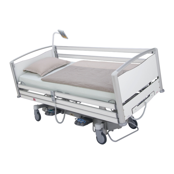
Linen Shelf with Attendant Control Panel Castor Control Lever Foot Control for Height Adjustment and Examination Position Foot Control for Lateral Tilt 150 mm Castor Full-length Siderail in lowered position NOTE For safe, easy handling, LINET® recommends that two technicians assemble the bed. D9U001L20-0101_04... -
Page 19: Technical Specification
Class I (with type B applied parts) Electrical Motor Operation Time max. 2 min ON / 18 min OFF NOTE Upon request, LINET® can deliver hospital beds with electrical specifications that comply with regional standards (custom voltage, different mains plugs). D9U001L20-0101_04... -
Page 20: Electromagnetic Compatibility
WARNING! Mobile RF communication device (including end use devices like antenna cables and external antenna) should not be used closer than 30 cm (12 inches) from any part of this bed Latera, including cables specified by manu- facturer. Otherwise this could lead to deterioration of functionality of this bed. WARNING! Do not overload the bed (SWL), respect the duty cycle (INT.) and consider chapter 18 Maintenance in order to maintain the basic safety with regard to electromagnetic disturbances for the expected service life. -
Page 21: Manufacturer Instructions - Electromagnetic Susceptibility
6.4.2 Manufacturer instructions - electromagnetic susceptibility Immunity Tests Compliance level Electrostatic discharge (ESD) ± 8 kV for contact discharge IEC 61000-4-2 ± 15 kV for contact discharge Radiated RF 3 V/m IEC 61000-4-3 80 MHz – 2,7 GHz 80 % AM at 1 kHz Proximity fields from RF wireless communications equipment IEC 61000-4-3 See Table 1... -
Page 22: Use And Storage Conditions
8.2 Bed Variants Basic models: ■ Latera Acute ■ Latera Thema Optional bed features for Latera Acute and Thema (standard = bold): ■ Siderails - type B applied parts □ Single siderail, powder-coated (Acute) □ Full-length siderail, aluminium with coloured plastic inlay, extendable (Thema) ■ Head Board and Foot Board - type B applied parts □ Plastic head board and foot board with coloured plastic inlay (Acute) -
Page 23: Putting Into Service
9 Putting into Service WARNING! Risk of injury when working on the bed! ► Ensure that the bed is disconnected from the mains connection prior to putting into service, putting out of service and maintenance. ► Ensure that the castors are locked prior to putting into service, putting out of service and maintenance. CAUTION! Material damage due to incorrect putting into service! ►... -
Page 24: Accumulator Activation
9.1 Accumulator Activation 9.1.1 Placement of Control Section 9.1.2 Removing the Isolating Foil PULL 9.1.3 Isolating Foil Check if isolating foil is complete and undamaged as shown: Fig. Isolating Foil NOTE It is advisable to wear protective gloves to prevent cuts from isolation foil. D9U001L20-0101_04... -
Page 25: Head Board And Foot Board
9.2 Head Board and Foot Board WARNING! Risk of injury when inserting the head board and foot board! ► To insert the head board and foot board into the corner posts, hold them by the corner handles on the top of the board. ► Install the head board and foot board before the first use. WARNING! Risk of injury due to incorrectly installed head board and foot board! ►... -
Page 26: Latera Thema Head Board And Foot Board
9.2.1 Latera Thema Head Board and Foot Board You can adjust the calfrest mechanically. A special locking mechanism allows the position to be adjusted. To remove the head board and foot board: Fig. Removing head board and foot board ►... -
Page 27: Potential Equalisation
9.3 Potential Equalisation The bed is equipped with a standard protective connector. This connector is used for potential equalisation between the bed and any intravascular or intracardiac device connected to the patient to protect the patient from static electric shocks. Fig. -
Page 28: Transport
9.5 Transport To avoid damage during transport, please observe the following guidelines: ► Ensure that no cables are run over when moving a bed. ► Ensure that the mains cable is attached with a hook (at the head end of the bed). ►... -
Page 29: Accumulator
Manufacturer provides 6 months warranty for full function of accumulators. The manufacturer takes no responsibility for any damage to the bed or accumulator caused by: ■ Not following instructions in the manufacturer´s instructions for use ■ Fitting accumulators which are not approved by LINET® ■ Accumulators fitted by an unqualified service organisation. To charge the accumulator: ►... -
Page 30: Replacing The Accumulator
11.1 Replacing the accumulator CAUTION! Damage to the bed due to incorrect accumulator replacement! ► Have the accumulator replaced exclusively by qualified personnel. ► Exclusively use accumulators approved by the manufacturer. WARNING! Risk of damage or destruction of accumulator! ► If accumulator is faulty degassing can occur. In rare cases this can cause deformation of the accumulator pack housing and mains control box. -
Page 31: Manipulation
12 Manipulation WARNING! Risk of injury when adjusting the bed! ► Ensure that there are no body parts between the mattress platform elements and the mattress platform frame when adjusting the bed. ► Ensure that there are no body parts below the mattress platform frame before adjusting the bed. ►... -
Page 32: Attendant Control Panel
12.1 Attendant Control Panel The Attendant Control Panel is the main control element. The Attendant Control Panel can be hung from the foot board if required. ► When not in use, store the Attendant Control Panel in the built-in linen holder below the foot board. 3 4 5 6 7 8 9 10 11 Fig. -
Page 33: Function Buttons
12.1.3 Function Buttons You can set different positions, for example the height and tilt of the mattress platform, adjust individual mattress platform elements, etc., with function keys 3, 6, 9, 12, 14 and 16. NOTE If you press two function buttons at the same time, the controller will recognise this as an error. The controller immediately interrupts all bed movements. - Page 34 Trendelenburg Position The Trendelenburg Position helps create anti-shock conditions for the patient. Settings after pressing position button 21: ■ All mattress platform elements are retracted to their lowest position. ■ The mattress platform is inclined by up to 16° (head lower than feet). The bed moves into the Trendelenburg position within 30 seconds from any mattress platform position.
-
Page 35: Handset
12.2 Handset A handset is included with the bed. The position of the handset depends on the patient’s condition. 1 2 3 1. Thighrest Adjustment Button 2. Thighrest/Backrest Lock LED ... -
Page 36: Foot Control Height Adjustment, Examination Position
12.3 Foot Control Height Adjustment, Examination Position The foot control is optional and allows you to set up the height of the bed with your feet. 1. Foot Control Lower Mattress Platform 2. Foot Control Examination Position 3. Protection Frame against Unwanted Activation 4. Foot Control Raise Mattress Platform Fig. -
Page 37: Satellite Panel
To prevent the trapping of extremities, use safety pillows to position the patient. ► If the weight limit is exceeded, use the CPR memory function to put the patient in a safe position. Latera Acute is equipped with the lateral tilt function. The lateral tilt is intended for: ■... -
Page 38: Cpr Backrest Release
12.7 CPR Backrest Release WARNING! Lowering the backrest too quickly can injure the patient! ► Ensure that the siderails are in the lowest position. ► Ensure that there are no body parts between the siderails and the backrest. ► Press the backrest down using the mattress guard handle only. The bed permits fast, mechanical lowering of the backrest for emergency resuscitation (CPR) procedures Fig. -
Page 39: Collapsible Siderails (3/4 Siderails)
12.8 Collapsible Siderails (3/4 siderails) WARNING! The hospital personnel is responsible for locking the siderails in the highest position when the patient is on the bed or when the bed is transported. WARNING! Ensure that there are no objects or body parts between the bars of siderail when folding the siderail up or down. Collapsible siderails are situated on both sides of the bed. -
Page 40: Full-Length Siderail Latera Thema
Take an upper edge of the siderail and push the siderail up. Siderail will click into place and lock automatically. ► Check if the siderail is fixed in place. 12.9 Full-length Siderail Latera Thema To adjust the siderails: ► Adjust the siderails by pulling on the top rail. The siderail will lock itself automatically. -
Page 41: Mattress Support Platform
12.10 Mattress support platform 12.10.1 Mechanical Calfrest Adjustment WARNING! Incorrect lowering can injure the patient! ► Hold the calfrest by both handles at all times when lowering the calfrest. ► Lower the calfrest carefully to prevent it from falling suddenly. You can adjust the calfrest mechanically. A special locking mechanism allows the position to be adjusted. To raise the calfrest: ►... -
Page 42: Undercarriage
12.11 Undercarriage CAUTION! Incorrect transport can damage the bed! ► Disconnect the bed from the mains before moving it. ► Store the mains cable in a safe place (plastic hook) on the bed during transport. ► Ensure that the castors are locked while the bed is stationary and prior to assembly, disassembly and maintenance. -
Page 43: Castor Control For Bed Without Control Levers
If the bed is stationary, activate the brakes. ■ Unplug the mains cord to move the bed. 14 Mattress The manufacturer recommends the use of the following mattress systems on the Latera Acute bed and Latera Thema bed: ► EFFECTACARE 20 ►... -
Page 44: Accessories
A plastic grab handle with an adjustable strap is attached to the lifting pole. NOTE The date of manufacture is marked on the grab handle. LINET® recommends that you replace the plastic grab handle every four years. Fig. Safety pin, locked in place... -
Page 45: Poles
15.2 IV Poles WARNING! Risk of injury due to use of unsuitable accessories! ► Use infusion stands exclusively for accessories listed in the instructions for use. ► Only mount an infusion pump to the lower (wider) telescopic section of an infusion stand above the head board / foot board. ►... -
Page 46: Plug And Play Adapter For The Handset
15.4 Plug and play adapter for the handset Fig. Plug and play adapter for the handset Adapter for simple connection and separation of the handset (e. g. when repairing, using the handset for other beds). 15.5 Writing Table Fig. Writing Table Writing table to be placed in the openings on the head board and foot board. -
Page 47: Urinary Bag Holder
15.7 Urinary bag holder Fig. Urinary bag holder Stainless steel holder for suspending urinary bags. The pivoting support piece allows the urinary bag to adjust to the bed position. 15.8 Urine bottle basket Fig. Urine bottle basket Basket for attaching and removing urine bottles. 15.9 Cannula Holder Fig. -
Page 48: Cleaning/Disinfection
Columns Oxidized aluminium alloy Undercarriage cover Acrylonitrile butadiene styrene (ABS) Corner covers only Latera Thema: High Pressure Laminate (HPL) + Oxidized aluminium alloy Corner bumpers Polypropylene (PP) Keyboards (Attendant Control Panel, Polyethylene terephthalate (PET) Handset, control elements integrated in the siderails) -
Page 49: Preparing For Cleaning
Cleaning agents LINET® recommends the following cleaning agents: Cleaning Agents Manufacturer Mikrozid, Terralin Protect, Thermosept Schülke & Mayr Bacillol AF, Bacillol Rasant, Dismozon Pur, Microbac Forte, BODE Chemie Neodisher Dekonta Lysoformin 3000, Lysoform Spezial LYSOFORM Incidin plus, Incidin rapid Ecolab Perform, TPH protect, Schülke... -
Page 50: Complete Cleaning And Disinfection
16.2.3 Complete Cleaning and Disinfection Clean the following bed parts: ► All of the control elements for adjusting the bed ► All handles ► Back and calfrest handles ► CPR release handle ► Head and foot boards including aluminium columns and crossbars under the boards ►... -
Page 51: Troubleshooting
17 Troubleshooting DANGER! Risk of mortal injury due to electric shock! ► If a fault occurs, have the electric motor, power box or other electrical parts repai- red by qualified personnel exclusively. ► Do not open the protective covers of the electric motor or the power box. Error/Fault Cause Solution... -
Page 52: Maintenance
Ensure that maintenance is performed exclusively by manufacturer´s customer service or by authorised service personnel certified by the manufacturer. ► If the defect cannot be repaired, do not use the bed. LINET ® recommends attaching the maintenance plaque to the bed. 18.1 Regular maintenance ► Check regularly movable parts for wear. -
Page 53: Disposal
Based on the Directive No. 2002/96/ EC (Directive WEEE - Waste, Electric and Electronic Equipments) the company LINET, s. r. o. is registered in the List of Electric and Electronic Equipment Producers (Seznam výrobců elektrozařízení) on the Ministry of the Environment of the Czech Republic... -
Page 54: Warranty
20 Warranty LINET ® will only be held responsible for the safety and reliability of products that are regularly serviced, maintained and used in accordance with the safety guidelines. Should a serious defect arise that cannot be repaired during maintenance: ►...
Need help?
Do you have a question about the LATERA and is the answer not in the manual?
Questions and answers