Sign In
Upload
Download
Table of Contents
Contents
Add to my manuals
Delete from my manuals
Share
URL of this page:
HTML Link:
Bookmark this page
Add
Manual will be automatically added to "My Manuals"
Print this page
×
Bookmark added
×
Added to my manuals
Manuals
Brands
LINET Manuals
Medical Equipment
LATERA ACUTE
Service manual
LINET LATERA ACUTE Service Manual
Hide thumbs
1
2
Table Of Contents
3
4
5
6
7
8
9
10
11
12
13
14
15
16
17
18
19
20
21
22
23
24
25
26
27
28
29
30
31
page
of
31
Go
/
31
Contents
Table of Contents
Troubleshooting
Bookmarks
Table of Contents
Table of Contents
1 Introduction - General Information
Product Label and Technical Label - Location
Product Label Description
Technical Label Description
Identification of Bed Parts
List of Tools and Equipment Needed for Servicing the Bed
2 Technical Data
Conditions of Use
Mechanical Data
Electrical Data
3 Components
Undercarriage
Central Braking System
Undercarriage Cover
Mattress Platform
Mechanisms of Mattress Platform
Head End Bar
Foot End Bar
Accesorry Rails
Electronic Equipment
Mattress Platform Actuators
Control Unit Pb45.X
Single Collapsible Side Rails
Full Length Side Rail
Battery Back-Up
4 Electrical Devices - Component Connections
Complete Wiring Diagram - Control Unit Pb45.X
Equipotential Bonding Connection
5 Bed Setting
Column Calibration
RC Circuit
Function Description and Purpose
Activating / Deactivating Short-Circuit Detection on the ACP
Electronic Safety Lock (Disabling Battery Back-Up)
6 Troubleshooting
Troubleshooting Table
Emergency Mode
Power Box Overheating
Transformer Overheating
One Fault State
Advertisement
Quick Links
Download this manual
77
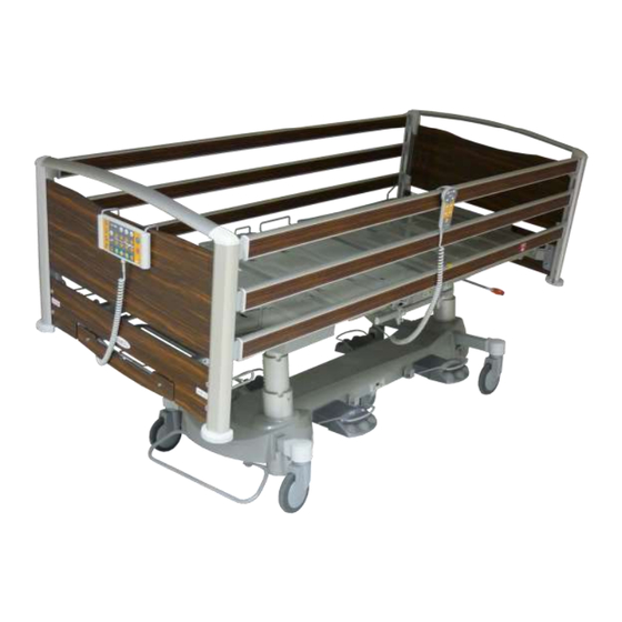
SERVICE MANUAL
LATERA ACUTE
LATERA THEMA
(according to 60601-2-52)
Date
05/2015
Version
02
Table of
Contents
Previous
Page
Next
Page
1
2
3
4
5
Advertisement
Table of Contents
Need help?
Do you have a question about the LATERA ACUTE and is the answer not in the manual?
Ask a question
Questions and answers
Related Manuals for LINET LATERA ACUTE
Medical Equipment LINET LATERA THEMA Service Manual
(31 pages)
Medical Equipment LINET LINIS SafetyPort Instructions For Use Manual
System for automated transfer and visualisation of various data from linet beds (52 pages)
Medical Equipment LINET LATERA Instructions For Use And Technical Description
Universal hospital bed (54 pages)
Medical Equipment Linet Image 3 B User Manual And Technical Description
Bariatric hospital bed for acute care (54 pages)
Medical Equipment LINET Eleganza 2 User Manual And Technical Description
A smart acute bed (76 pages)
Medical Equipment LINET Eleganza 3 User Manual And Technical Description
Positionable hospital bed for acute care (56 pages)
Medical Equipment LINET Eleganza 3 User Manual And Technical Description
Positionable hospital bed for acute care (52 pages)
Medical Equipment LINET Essenza 300 Instructions Manual
Medical bed for acute care and long-term care (200 pages)
Medical Equipment LINET Virtuoso User Manual And Technical Description
Antidecubitus system, mattress replacement system series 2 (37 pages)
Medical Equipment Linet TOM 2 USA Service Manual
Pediatric hospital bed (48 pages)
Medical Equipment Linet Eleganza Classic Operation Manual And Technical Description
Cabinets (15 pages)
Medical Equipment Linet MULTICARE 2015 Service Manual
(84 pages)
Medical Equipment Linet Tom 2 User Manual And Technical Description
Paediatric hospital bed (58 pages)
Medical Equipment LINET Sprint 100 User Manual And Technical Description
Universal transport stretcher (60 pages)
Medical Equipment LINET Air2Care 10 User Manual And Technical Description
Mattress replacement and overlay systems (43 pages)
Medical Equipment LINET Multicare LE User Manual And Technical Description
Positionable bed for intensive care and integrated mattress replacement system for multicare le (85 pages)
This manual is also suitable for:
Latera thema
Table of Contents
Print
Rename the bookmark
Delete bookmark?
Delete from my manuals?
Login
Sign In
OR
Sign in with Facebook
Sign in with Google
Upload manual
Upload from disk
Upload from URL


Need help?
Do you have a question about the LATERA ACUTE and is the answer not in the manual?
Questions and answers