Advertisement
Quick Links
Item: SD-FRLS05701**
SD-FRLS05702**
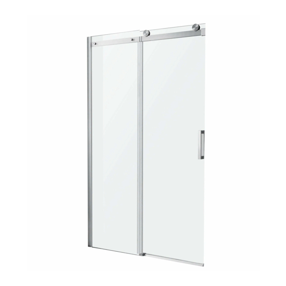
ANZZI GLASS SHOWER DOOR
INSTALLATION & OPERATION MANUAL
V2.2
DON'T WAIT!
REGISTER NOW!
Register your product within 90 days to ensure your product is
recognized as an official purchase and is eligible for warranty
coverage.
Mail in the completed registry card (Pg. 2) or register online
at
www.swcorp.com/register
.
V2.2 – This version supersedes all previous versions as of 3/31/2022
Advertisement

Subscribe to Our Youtube Channel
Related Manuals for Anzzi SD-FRLS05701 Series


Summary of Contents for Anzzi SD-FRLS05701 Series
- Page 1 Item: SD-FRLS05701** SD-FRLS05702** ANZZI GLASS SHOWER DOOR INSTALLATION & OPERATION MANUAL V2.2 DON’T WAIT! REGISTER NOW! Register your product within 90 days to ensure your product is recognized as an official purchase and is eligible for warranty coverage. Mail in the completed registry card (Pg. 2) or register online www.swcorp.com/register...
- Page 3 Please check the product for damage and missing parts immediately upon delivery. Damage reported later will not be covered by our warranty. Please handle the product with care. Avoid any impact to the sides and edges of the glass. is being (if required by local code) plumber for all plumbing installations.
-
Page 4: Before You Begin
INSTALLATION GUIDE BEFORE YOU BEGIN ATTENTION Threshold must be level for proper installation. The installation of this unit requires that you drill down into the threshold. Contact the manufacturer of the base or threshold material with any questions regarding the drilling of holes into their product. - Page 5 PARTS [05] x1 [09] x1 [10] x1 [01] x1 [02] x1 [03] x1 [04] x1 [06] x1 [07] x1 [08A] x1 [08B] x1 [11] x1 [12] x2 [13] x2 [14] x2 [15A] x1 [15B] x1 [16A] x1 [16B] x1 [17] x1 [18] x1 [19] x2(ST5x35mm [20] x4(ST4x35mm...
- Page 6 ASSEMBLY [02] [13] [14] [03] [07] [18] [08B] [08A] [10] [22] [20] [19] [12] [09] [06] [01] [11] [17] [15B] [23] [24] [05] [16B] [21] [04] Part Description Qty. Part Description Qty. [01] Magnetic Wall Column [13] asteners [02] Wall Jamb [14] Wheel Guard [03]...
- Page 7 SD-FRLS05701**48"*76" 1.8" [648 25.5" 22.2" 563mm [1209-1224 47.6"-48.2"...
- Page 8 SD-FRLS05702**60"*76" 1.8" [800 31.5" [715 28.1" [1514-1529 59.6"-60.2"...
-
Page 9: Installation Instructions
ATTENTION To avoid personal injury or property damage, identify components and read all instructions before installing. This model requires a minimum 2-3/16" (55mm) of flat level threshold space for installation. (Dimension "D" of Fig 2.) The instructions below are for installing the fixed panel on the right. To install the fixed panel on the left, transpose all instructions. - Page 10 Step 2 Remove Wall Jamb [02] and drill a 1/4" hole at each location marked for Wall Jamb [02] (Fig 3). ATTENTION Wear safety glasses and cut-resistant, non-slip gloves when drilling or cutting to avoid risk of injury. Fig 3 Step 3 1.Insert Anchor [22] in each hole location.
- Page 11 Step 4 Place the Wall Jamb [02] onto the wall. Use drill to start the ST4x35 screw [20] into the Anchor [22]. Use a screwdriver to hand tighten until secure. (Fig. 5) [20] Fig 5 Step 5 1.Carefully lay your glass panels flat on a soft, padded surface to inspect the glass.
- Page 12 Step 6 1.Using a level, check that Fixed Panel [10] is level vertically (Fig 7). 2. Install the Gasket [07]. (Fig 7.1) [07] Fig 7 Step 7 1.Check that the measurement from front of wall to Fixed Panel [10] is the same at both ends of the panel (Fig 8.1).
- Page 13 Step 8 1.Measure the fi nished opening width at the model height ("W1"). IMPORTANT: If the Support Bar [03] matches the width, there's no need to cut it. If it doesn't, please see Step 2 for cutting instructions (Fig 9.1). 2.Using a pencil or another marking tool (such as masking tape), mark distance "W1, minus 11/16"...
- Page 14 Step 9 1.Unscrew screw "a" and tighten screw" b". Unscrew screws "c" and "d" until the screws do not protrude from the inside surface. Keep the screws in the Wall Bracket [18] (Fig 10.1). 2.Install the Wall Bracket [18] to the Support Bar [03]. Slightly tighten the screw "d" (Fig 10.2).
- Page 15 Step 10 1.Using a pencil or other marking tool (such as masking tape), mark the position of the Wall Bracket [18] (Fig 11.1). 2.Remove the Support Bar [03] and remove the Wall Bracket [18] from the Support Bar [03]. 3.Mark the screw hole locations (Fig 11.2). 4.Drill a 1/4"...
- Page 16 Step 11 1.Disassemble the gasket and anchor from the Wall Bracket [18]. Attach the gasket and anchor to wall using Screw ST5x35 [19]. Use drill to start screws into anchor. Next, use a screwdriver to hand tighten until secure (Fig 12.1). 2.Slide bracket sleeve onto end of Support Bar [03] (Fig 12.2).
- Page 17 Step 12 Depending on which side of the Fixed Panel [10] is installed, either Bottom Guide (L&R) [15] will be used. For this left side opening, Bottom Guide [15B] will be shown being installed. Mark center guide hole location. 1.Push the button of the Bottom Guide [15] to disassemble it into part a and b (Fig 13.1). 2.Place part a into correct position against the Fixed Panel [10] and mark the hole location (as shown in Fig 13.2).
- Page 18 Step 13 1.Using provided adjustment Wrench [21], disassemble Trolley Wheel [12] as shown in (Fig 14.1). Repeat for the remaining Trolley Wheel [12] . 2.Install Trolley Wheel [12] to the Door Panel [09]. The washer should be on the metal part side (Fig 14.2).
- Page 19 Step 14 1.From inside of enclosure, carefully, and with assistance from another capable person, hang sliding Door Panel [09] and Trolley Wheel [12] assemblies onto Support Bar [03] (Fig 15.1). 2.Disassemble Wheel Guard [14] as shown in Fig 15.2. 3.From inside enclosure, install Wheel Guard [14] to inside of sliding Door Panel [09] as shown in Fig 15.3.
- Page 20 Step 15 1.Measure the distance between the Bottom Guide [15] and the door side wall ("W1").The length of Threshold Gasket [05] would be "W1, minus 1-3/16 (30mm )" (Fig 16.1). IMPORTANT: if the Bottom Rail [04] and the Threshold Gasket [05] match the width. There's no need to cut them.
- Page 21 Step 16 1. Check that the measurement from front of wall to Bottom Rail [04] is the same at both ends of rail and mark using the pencil (Fig 17.1). 2.Install the Threshold Gasket [05] as shown in Fig 17.2. 3.Apply silicone to the Bottom Rail [04] and install it against the Bottom Guide [15] (Fig 17.3 and Fig 17.4).
- Page 22 Step 17 1. Attach the Magnetic Gasket [06] to the Door Panel [09] close to the side wall as shown in Fig 18.1. 2.If the Side Gasket [08] is longer than the panels after installation. cut it to correct length. Cut the part of the Side Gasket [08] that is interfering with the Support Bar [03] as shown in Fig 18.2.
- Page 23 Step 18 1. Attach the Magnetic Wall Column [01] to the installed Magnetic Gasket [06]. Make sure the Magnetic Wall Column [01] aligns to the center of the door panel as shown in Fig 19.1. 2.Slide the Door Panel [09] to the wall which is in contact with the Magnetic Wall Column [01].
- Page 24 Step 19 1. If needed, the door height at each wheel can be individually adjusted by using the Wrench [21]. a. For the Trolley Wheel [12], use a Wrench [21] to carefully loosen the nut half a turn. Rotate plastic nut as shown in Fig 20.1. This will raise or lower the Door Panel [09] at this location so that the door panel can match the wall better.
- Page 25 Step 20 1. Disassemble Handle Set [11] by loosening the screws (Fig 21.1). 2. Install handles and gaskets on both sides of the Door Panel [09] as shown in Fig 21.2. The handle with screw holes faces inside. 3. Tighten the screws to secure the Handle Set [11]. IMPORTANT: DO NOT over tighten the screws.
- Page 26 Step 22 1. To install the Door Panel [09] on the left: Use Bottom Guide [15B] and Seal [16B] (Fig 23). 2. To install Door Panel [09] on the right: Use Bottom Guide [15A] and Seal [16A] (Fig 24). [15B] [16B] Fig 23 [15A]...
-
Page 27: Care And Maintenance
Never use an abrasive sponge or cloth, steel wool, or wire brush, which may permanently scratch the surfaces. NOTE: Regularly inspect the glass and all hardware for misalignment, proper attachment, and damage. Contact ANZZI with any questions or concerns.
Need help?
Do you have a question about the SD-FRLS05701 Series and is the answer not in the manual?
Questions and answers