Chapters
Table of Contents

Subscribe to Our Youtube Channel
Related Manuals for FMS EDF Jet 70mm F-18F V2 PNP


Summary of Contents for FMS EDF Jet 70mm F-18F V2 PNP
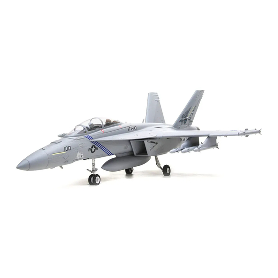
- Page 1 70mm F/A-18F Instruction Manual Bedienungsanleitung Manuel d’utilisation 操作手册 REALISTIC RIGID STABLE FMSMODEL.COM Retracts and flaps installed Durable EPO material Smooth flying performance...
- Page 2 WARNING WARNING: Read the ENTIRE instruction manual to become familiar with the features of the product before operating. Failure to operate the product correctly can result in damage to the product, personal property and cause serious injury. This is a sophisticated hobby product and NOT a toy. It must be operated with caution and common sense and failure to do so could result in injury or damage to the product or other property.
-
Page 3: Table Of Contents
• Includes 4 different decal sets for trim scheme customization. in 2006; the Super Hornet serves alongside the original Table of Contents Hornet. FMS is proud to present the 70mm F/A-18F with an unprece- dented amount of innovative features and attention to scale Introduction ···························································... -
Page 4: Model Assembly
Model assembly Main Wing Installation 1.Align and insert the wing spar into the wing tubes, then slide the wing spar into the fuselage. Note: The connectors on both sides should be attached precisely and firmly. 2.Secure both wings to the fuselage using the included screws. - Page 5 Model assembly Vertical stabilizer installation Vertical Stabilizer Installation 1.Slide the vertical tail into the slot in the fuselage. 2.Secure the vertical tail in place using the included screws. Note: Connect the rudder servo connectors to the servo extensions in the fuselage. Missiles and Oil Tank Installation 1.Slide the missiles and oil tank into the rails.
-
Page 6: Battery Installation
Model assembly Nose cone installation 1.Attach the nose cone to the front of the fuselage; the nose cone is held in place with a magnet. Please note that the orientation of the nose cone is correct. Battery installation 1.Pull back on the latch, releasing the canopy. 2.Remove the canopy, revealing the battery compartment. - Page 7 Battery installation Get your model ready to fly Important ESC and model information The ESC included with the model has a safe start. If the motor battery is connected to the ESC and the throttle stick is not in the low throttle or off position, the motor will not start until the throttle stick is moved to the low throttle or off position. Once the throttle stick is moved to the low throttle or off position, the motor will emit a series of beeps.
-
Page 8: Get Your Model Ready To Fly
Get your model ready to fly Check the control throws The suggested control throw setting for the F/A-18F are as follows (dual rate setting): Tips: On first flight, fly the model in low rate. The first time you use high rates, be sure to fly at low to medium speeds. -
Page 9: Before Flying The Model
Before flying the model Flying your model Find a suitable flying site Take off Find a flying site clear of buildings, trees, power lines and While applying power, slowly steer to keep the model straight. other obstructions. Until you know how much area will be The model should accelerate quickly. -
Page 10: Troubleshooting
Troubleshooting Problem Possible Cause Solution Aircraft will not respond to - Lower throttle stick and throttle trim to lowest settings - ESC is not armed the throttle but responds - Reverse throttle channel on transmitter - Throttle channel is reversed to other controls - Replace damaged fan unit - Damaged blades... -
Page 11: Decal Instruction
ESC instruction Decal instruction Please choose one set of decals to apply to your aircraft according to your personal preference. Water decal instructions. The included decals are water decals, they do not have adhesive backings thus are not applied like usual stickers. - Page 13 Warnhinweise WARNUNG: Lesen Sie die GESAMTE Bedienungsanleitung, um sich vor der Inbetriebnahme mit den Funktionen des Produkts vertraut zu machen. Wenn das Produkt nicht ordnungsgemäß bedient wird, kann dies zu Schäden am Produkt oder persönlichem Eigentum führen und schwere Verletzungen verursachen. Dieses Produkt ist kein Spielzeug! Es muss mit Vorsicht und gesundem Menschenverstand betrieben werden.
-
Page 14: Einleitung
Einleitung Inhaltsverzeichnis Einleitung Die F/A-18 Super Hornet von FMS mit einer Spannweite von ····························································· 104 cm ist ein sehr detailliertes Modell aus EPO Schaum. Das Lieferumfang ························································· 13 Modell zeichnet sich durch viele neue Konstruktions- und Montage des Modells ·············································· 14... -
Page 15: Montage Des Modells
Montage des Modells Montage der Tragflächen 1.Schieben Sie das Steckungsrohr in den Rumpf und stecken Sie dann beide Flügel in den jeweils vorgesehenen Schlitz im Rumpf. Hinweis: Die Anschlüsse an beiden Seiten sollten genau und fest angebracht sein. 2. Sichern Sie die Tragflächen bei den beiliegenden Schrau- ben. - Page 16 Montage des Modells Vertical stabilizer installation Montage des Seitenruders 1.Stecken Sie das Leitwerk in den Schlitz am Rumpf. 2.Befestigen Sie das Leitwerk mit den mitgelieferten Schraben. Hinweis: Schließen Sie die Servo-Kabelstecker an die Kabel im Rumpf an. Montage der Raketen 1.Stecken Sie die Raketen wie abgebildet in die entsprechen- den Vorrichtungen Installation der Scale Teile...
-
Page 17: Anschluss An Den Empfänger
Montage des Modells Anstecken der Nase 1.Bringen Sie die Nase wie gezeigt an den vorderen Rumpf Einsetzen des Flugakkus 1.Entfernen Sie die Kabinenhaube und öffnen die Akkubefes- tigungslaschen. 2. Befestigen Sie das Klettband am Akku. 3. Schieben Sie den voll geladenen Akku ans hintere Ende des Rumpfes in das Akkufach. -
Page 18: Flugvorbereitungen
Battery installation Flugvorbereitungen Wichtige Informationen zum Regler Der eingebaute Regler ist mit einer Sicherheitsschaltung versehen. Sollte der Akku angeschlossen sein und der Gashebel nicht auf niedrig / Motor aus stehen, wird der Motor nicht starten. Wird der Gashebel ganz nach unten bewegt erzeugt der Regler eine Tonserie. -
Page 19: Ruderausschläge
Flugvorbereitungen Ruderausschläge Die empfohlenen Ruderausschlag-Einstellungen sind (Dual Rate): Tips: Fliegen Sie das Modell beim ersten Flug maximale Ausschläge normale Ausschläge mit "normalen Ausschlägen". Wenn Sie zum Höhenruder 16mm oben / unten 12mm oben / unten ersten Mal "maximale Ausschläge" verwenden, sollten Sie bei niedrigen bis mittleren Geschwind- Querruder 14mm oben / unten... -
Page 20: Vor Dem Erstflug
Vor dem Erstflug Fluggrundlagen Finden Sie einen geeigneten Flugplatz Starten Finden Sie seinen Flugplatz frei von Gebäuden, Bäumen, Beschleunigen Sie das Modell vorsichtig und steuern Sie es Stromleitungen und anderen Hindernissen. Bis Sie wissen, langsam um es gerade zu halten. Erhöhen Sie die Beschleuni- wie viel Fläche Sie zum fliegen brauchen, wählen Sie einen gung und halten Sie eine gleichmäßige Geschwindigkeit um Platz der mindestens die Größe von 2 bis 3 Fussballfeldern... -
Page 21: Problemlösungen
Problemlösungen Problem Mögliche Ursache Lösung Modell nimmt kein Gas - Gasknüppel ist nicht ganz unten oder Trimmung zu hoch - Regler reagiert nicht an,andere Steuerungsbe- - Gaskanal am Sender umkehren - Gaskanal ist umgekehrt fehle funktionieren aber - Spinner,Propeller,Motor oder - Defekte Teile austauschen Ungewöhnliche Propel-... - Page 22 Dekorbogen aufbringen ESC instruction Wählen Sie eins der Dekore aus und bekleben das Modell wie abgebildet. Wasser Aufkleber aufbringen Die verschiedenen Dekore sind Wasserabziehbilder. Bitte nur wie unten angegeben lösen / aufbringen. 1. Stellen Sie sicher, dass Ihre Hände trocken sind, und schneiden Sie das Abziehbild vorsichtig mit der Schere aus. 2.
- Page 24 ATTENTION ATTENTION : Lisez intégralement ce manuel d’utilisation pour vous familiariser avec les caractéristiques de ce produit avant de l’utiliser. Ne pas utiliser correctement ce produit peut entraîner des dommages au produit, aux biens matériels et causer des blessures graves. Il s’agit d’un produit de loisir technique, sophistiqué, et non d’un jouet.
-
Page 25: Introduction
Tomcat, qui ont été totalement retirés en 2006. Les Super Table des matières Hornet sont en service en parallèle avec les Hornet d'origine. FMS est fier de vous proposer ce tout nouveau et très détaillé F/A-18F Super Hornet à turbine électrique de 70 mm. Il intègre Introduction ··························································... -
Page 26: Montage Du Modèle
Montage du modèle Installation des ailes 1. Glissez le tube dans le fuselage puis montez les deux ailes sur les tube de clé d'aile et dans les logementsd'ailes du fuselage. 2. Fixez les deux ailes au fuselage à l'aide des vis fournies. Installation des stabilisateurs horizontaux 1. - Page 27 Montage du modèle Vertical stabilizer installation Installation des empennages verticaux 1.Branchez les connecteurs des servos de direction sur les 2.Fixez les dérives en place à l'aide des vis fournies. rallonges dans le fuselage. Note: Glissez les dérives dans les fentes du fuselage. Montage des missiles et du réservoir de carburant 1.Glissez les missiles et le réservoir dans les rails.
-
Page 28: Mise En Place De L'accu
Montage du modèle Montage du cône de nez 1.Placez le cône de nez à l'avant du fuselage comme montré sur le schéma. Vérifiez que le cône est dans le bons sens. Mise en place de l'accu 1.Poussez en arrière le verrou et déposez la trappe d'accès aux accus. - Page 29 Battery installation Préparation du modèle au vol Informations importantes concernant le contrôleur brushless et le modèle Le contrôleur brushless inclus dans votre modèle est équipé d'un démarrage sécurisé. Si l'accu de propulsion est branché au contrôleur alors que le manche de gaz n'est en position moteur coupé, le moteur ne démarrera pas tant que le manche n'aura pas été...
-
Page 30: Préparation Du Modèle Au Vol
Préparation du modèle au vol Contrôle des débattements Les débattements conseillés pour votre modèle FMS sont les suivants (Réglages de doubles débattements): CONSEILS: Pour le premier vol, pilotez le Grands débattements Petits débattements modèle avec les petits débattements.La première Profondeur... -
Page 31: Avant De Faire Voler Le Modèle
Avant de faire voler le modèle Pilotage du modèle Trouvez un site de vol adapté Décollage Trouvez un site de vol dégagé, à l'écart de bâtiments, En mettant progressivement les gaz, maintenez l'axe avec la d'arbres, de lignes électriques ou autres obstacles.Jusqu'à ce direction, le modèle va accélérer rapidement. -
Page 32: Dépannage
Dépannage Problème Cause possible Solution Le moteur de l'avion ne ré- - Abaissez le manche de gaz et son trim tout en bas - Le contrôleur n'est pas armé pond pas, mais les autres - Inversez la voie des gaz sur l'émetteur - La voie des gaz est inversée commandes répondent - Cône, hélice, moteur ou support... - Page 33 Instruction de pose des décalcomanies ESC instruction Choisissez un des jeux de décalcomanies selon vous goûts et choix historiques et collez-les comme montré. Instructions de pose des décalcomanies à l'eau La planche ci-dessus est composée de décalcomanies à l'eau. Ne les forcez pas à sortir du papier support. Suivez ces instructions : 1.Assurez-vous d'avoir les mains sèches.
- Page 35 警告 警告: 在组装、 调整及飞行前请务必认真阅读产品说明书以熟知产品的特性。 请严格按照说明书提示进行飞机的组装、 调整及飞 行。 如操作不当会造成产品本身损坏及其它财产损失, 甚至造成严重的人身伤害。 声明: 模型不是玩具, 具有一定的危险性, 操作者需要具备一定的飞行经验, 初学者请在专业人士指导下操作。 禁止十四岁以下儿 童操作、 飞行。 安全须知 本产品飞行由无线电遥控器控制, 在飞行过程中可能会受到外界强信号源干扰而导致失控, 甚至坠机。 因此, 在飞行过程中务必始 终与飞机保持一定的安全距离, 避免意外碰撞、 受伤。 ⸺请勿在发射器电池低电量的情况下操纵模型飞机。 ⸺请勿在公路、 人群、 高压线密集区、 机场附近及其它法律法规明确禁止飞行的场合飞行。 ⸺请勿在雷雨、 大风、 大雪或者其它恶劣气象环境下飞行。 ⸺请严格遵照产品指导说明及安全警告操作本产品及其相关配置 (例如充电器、 电池等) 。 ⸺请勿将相关化工类产品、 零部件、 电子部件等置于儿童可触及的范围。 ⸺请勿将电子件暴漏于潮湿的环境中,...
- Page 36 蜂作为已取消的 A-12 舰载攻击机的替代方案,最初在 1995 年 12 月试飞,并在 1997 年 9月波音和麦道公司正式合并前的一个 5. 便捷的螺丝组装结构。 月开始量产。1999年起超级大黄蜂陆续进入美国海军服役,以取 6. 卡扣式座舱结构,安全牢固。 代老迈的 F-14 “雄猫式”战斗机和 A-6 “闯入者”式攻击机。 7. 四款个性贴纸,DIY 属于你自己的“超级大黄蜂”。 因此,超级大黄蜂继承了两种攻击形式,而成为 21 世纪初期美 国航空母舰舰载机的唯一主力。 目录 FMS 很荣幸给大家带来这款高复原度的 70mm 涵道 F/A-18F 超 级大黄蜂。 产品特点 ····························································· FMS70mm涵道超级大黄蜂,在当下畅销的64mm大黄蜂的基 产品组成 础上,做了许多方面的改进。它优化了机型轮廓,精准了表面 ····························································· 33 机体安装 刻线,完善了动力系统,除此之外,它采用了卡扣式座舱,玩...
- Page 37 机体安装 主翼安装 1. 把主翼对接管插入机身槽位,安装左右两侧机翼。 注意: 机翼和机身的对接插头请确保插牢。 2. 使用所附螺丝固定机翼。 平尾安装 1. 连接平尾舵机和机身的舵机延长线。 注意: 平尾和机身的对接插头请确保插牢。 2. 如图所示, 在机身尾部凹槽的底部和壁部使用泡沫胶, 安装平尾。 泡沫胶示意图...
- Page 38 机体安装 垂尾安装 Vertical stabilizer installation 1.连接垂尾舵机和机身的舵机延长线。 ( 如图所示, 将垂尾安装 2. 如图所示, 使用所附螺丝固定垂尾。 注意: 垂尾和机身的对接插头请确保插牢。 安装导弹和副油箱 1.如图所示, 安装导弹和副油箱。 像真塑胶件安装 1.在图示槽位的底部和壁部打胶。 2.将像真塑胶件安装到位。...
- Page 39 机体安装 飞机头罩安装 1.如图所示 , 安装机头罩 , 确保机头罩安装方向无误。 电池安装 1.打开座舱卡扣, 移开座舱。 2.取下电池板上的魔术贴 (毛面) 贴于电池上面。 3.如图所示, 将电池置于电池舱内, 用魔术带绑紧, 使有电源线 的那端朝向飞机的尾部。 注意: 平尾和机身的对接插头请确保插牢。 接收机连接示意图 Récepteur 如图所示, 以 Futaba 遥控器为例, 将副翼舵机信号线插入接收 副翼 机副翼通道、 升降舵舵机信号线插入接收机升降舵通道、 方向舵 Channel-1 平尾 舵机信号线插入接收机方向舵通道、 电调信号线插入接收机油 - Aile Channel-2 门通道。 油门 Elve 最后将所有连接线整理整齐并固定在电池仓后部的凹槽内,...
- Page 40 遥控器设置 Battery installation 警告: 为保证安全, 在遥控器参数设置及舵面调整过程中, 请务必拆下螺旋桨, 以免电机意外启动发生事故。 遥控 器发射机开机前, 确保油门杆在最低位置, 其它摇杆在中立位置。 开发射机并给接收机通电, 随后听到电调初始化音 (音符释义见后文 “电子调速器说明书” ) 。 观察所有舵面是否回中, 如果没 有回中, 尽量通过调整舵机摇臂角度、 连杆长度的方式来使舵面回中, 若调整长度在安全范围内仍未回中, 则使用遥控器通道 微调或者菜单中的 “SubTrim” 选项来使舵面归中。 如下图所示观察摇杆动作与舵面动作的对应关系, 如发生舵面反向需要使 用遥控器中的通道反向功能来纠正。 爬升 1. 移动发射器上的控制杆位置,确保舵面可以自如移 升降 动(如下图)。 降落 转左 左推 副翼 转向...
- Page 41 舵角和舵机摇臂安装 舵角 摇臂 大舵面 平尾 图示是舵角和舵面摇臂的出厂设置。首飞建议用出厂设 置的小舵角飞行。首飞后,可按图调整舵角。 小舵面 垂尾 副翼 重心调整 通过移动电池在电池舱内的前后位置调整飞机的重心 ,使飞机 保持水平或稍微头重的状态。首飞以后重心位置可以根据你自 60-70mm 己的飞行偏好再做更改。 1.如图所示,推荐重心位置是机翼前缘往后 60-70mm 处(安 装电池以后)。推荐把食指放在机翼下面的重心位置来帮助 调整重心。 2.在调整飞机重心的时候请确定飞机处于组装完毕待飞的状 态。 飞行前准备 起飞前的检查 每次飞行前须做严格的地面检查,可有效避免飞行事故 1. 检查全机螺丝是否安装到位、舵角摇臂连接可靠。机翼快拆装置已锁紧。 2. 安装电池,并调整飞机重心到说明书推荐位置。 3. 动力电池、遥控器发射机电池等已充满电,处于可靠工作状态。 4. 发射机油门杆保持在最低位(推荐使用带有油门锁定功能的遥控设备),打开发射机,随后连接动力电池,待电调初始 化完成后检查各个舵面是否回中,是否动作正确。 5. 轻推油门观察螺旋桨转向是否正确。 所有检查完成后,方可进行飞行,初学者首次飞行需要有经验的爱好者协助完成,避免因操作不当发生飞行事故。 合适的飞行场地 航模飞行须远离人群、建筑物、树木、高压线及禁飞区的空旷场地(至少 2-3 个足球场大小)。初学者飞行前需要向有经 验的爱好者询问相关安全事宜。...
- Page 42 70A 电调 (线长 300mm) ROCK0111 PRESC013 主起落架组 9G 数字金属舵机正 ROCK0112 FMSSER9MGDP 前起落架系统 9G 数字金属舵机反 ROCK0113 FMSSER9MGDR 请登陆 FMS 官网查看产品图片 : www.fmsmodel.com 故障检修指导 问题 问题原因 解决方式 油门推杆无响应,但舵机 - 电调未连接电机 - 降低油门推杆和油门微调设定 有响应 - 油门通道反向 - 反过来重新装油门通道 - 桨罩、 桨、 电机、 电机架坏了...
- Page 43 贴纸说明书 请参考历史资料或依据个人偏好, 在以下贴纸中选出一套, 按照所列的步骤粘贴。 水贴安装方法 : 以上几个是水贴, 请不要尝试强行撕下。 1. 用剪刀剪下你需要用到的水贴 (注意不要剪破透明部分) 2. 把剪下的水贴放到水里, 让纸张完全吸水。 把 贴 纸 靠 近 飞 机 对 应 位 置 , 然 后 慢 慢 把 贴 纸 移 出 , 吸 附 在 飞 机...
Need help?
Do you have a question about the EDF Jet 70mm F-18F V2 PNP and is the answer not in the manual?
Questions and answers